Horizontal Stabilator Progress – A Family Job

Where the heck have we been?

It is unfortunate that I’m both posing and answering this question again. Work took its toll in the last year and we did not get a lot of building done (some overtime though, which is always good for the airplane fund!) . The delays and much slower than expected build in the last year or so set us back behind our originally planned build timeline but has made the “financial” schedule slightly easier to meet. Now it’s time to recoup momentum and get going!


2019 Stabilator Build Progress & Workshop Upgrade Summary

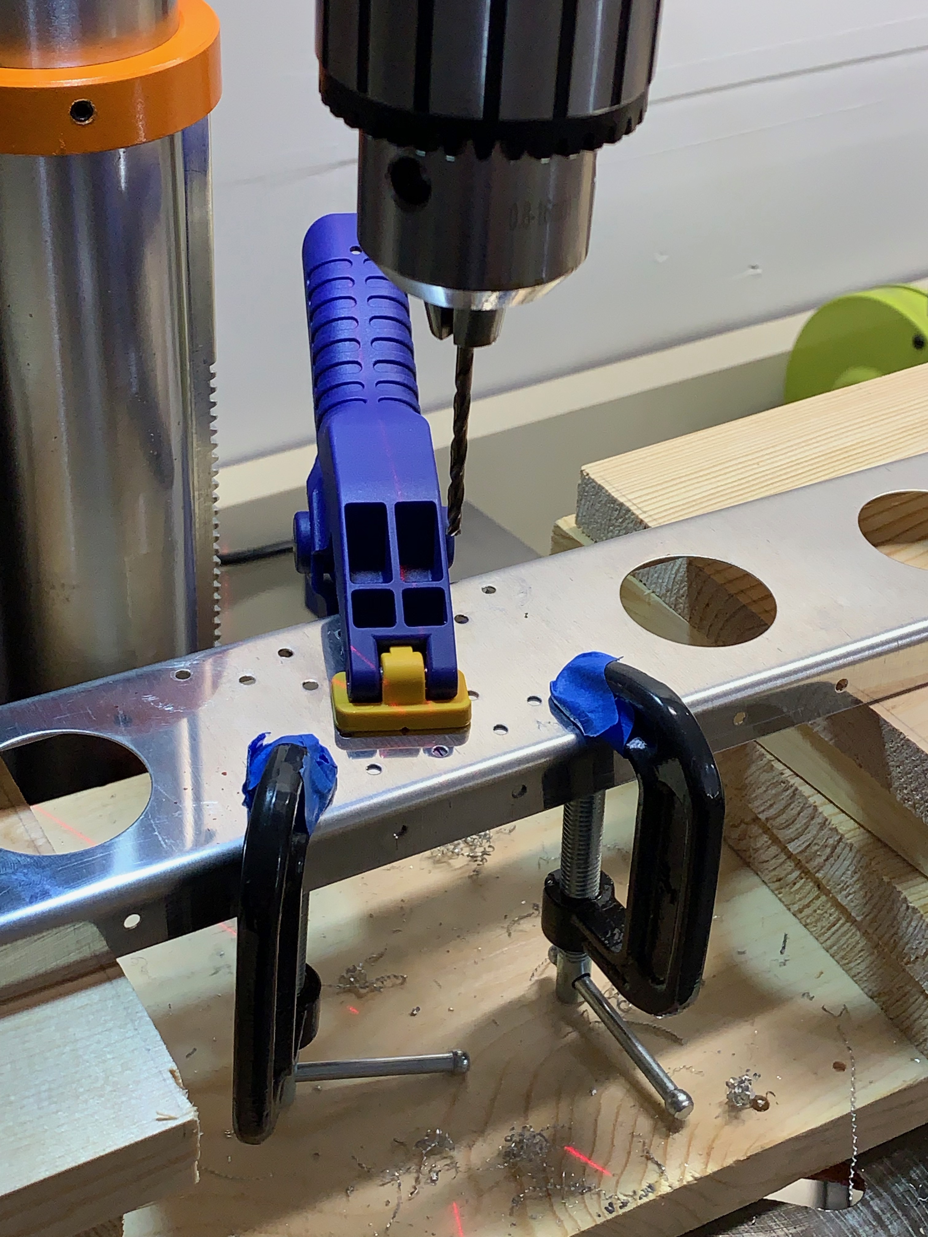
This is a bit of a catch-up post covers that about 50 hours of work between me, Kelsey and my parents (Greg and Denise) on the Horizontal Stabilator. We worked on and off (mostly off) from March to the end of September 2019. My parents were especially helpful in some improvements to the garage workspace! We built two new EAA Chapter 1000 workbenches(with slight height modifications) in April, which you will see below. Then they returned in June and helped us work on the stabilator a bit. Thanks for the help, mom and dad!

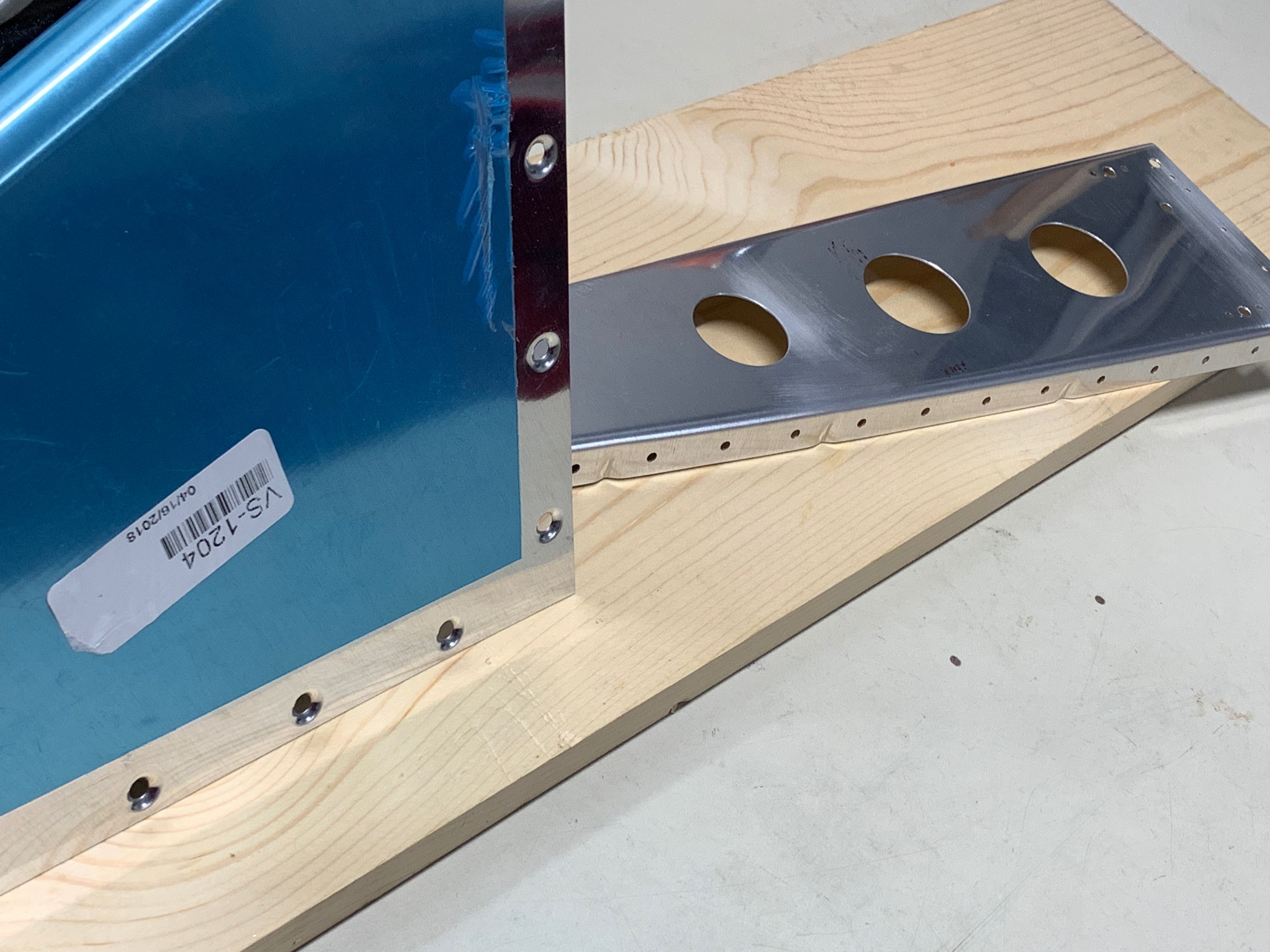
I started the initial deburring of the Horizontal Stabilator spar box components in late February 2019. The spar box carries the lift load for the horizontal tail. Here’s a close-up of a the nice shiny aft spar the day before priming:

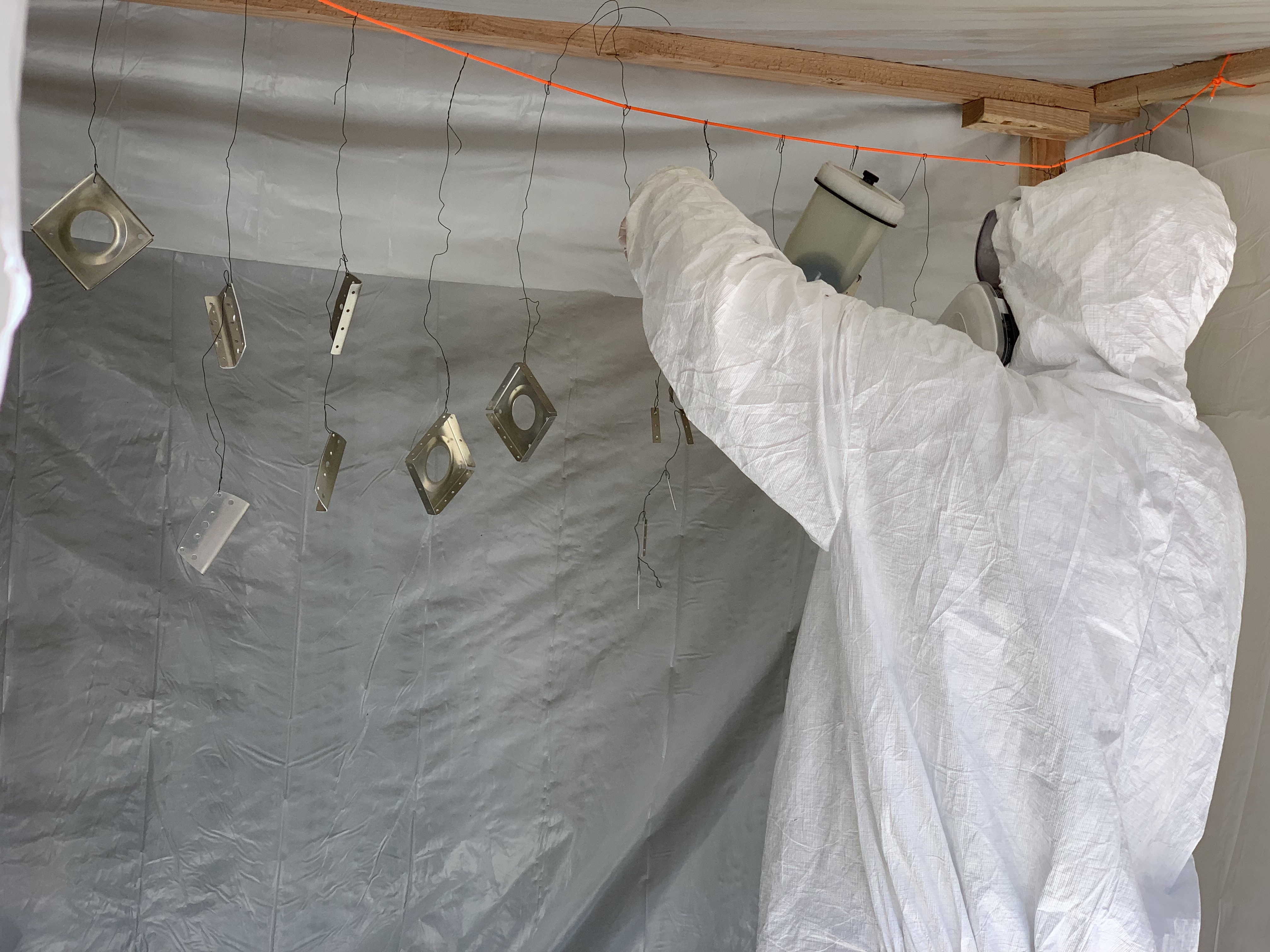
We primed the Horizontal Stabilator spar box pieces on 3/31/19. This was the last planned prime with the Sherwin Williams P60G2. We decided that the stuff is just a little too nasty to keep spraying. Stewart Systems Ekoprime is what we switched to – more on that in a later post.

img_1800


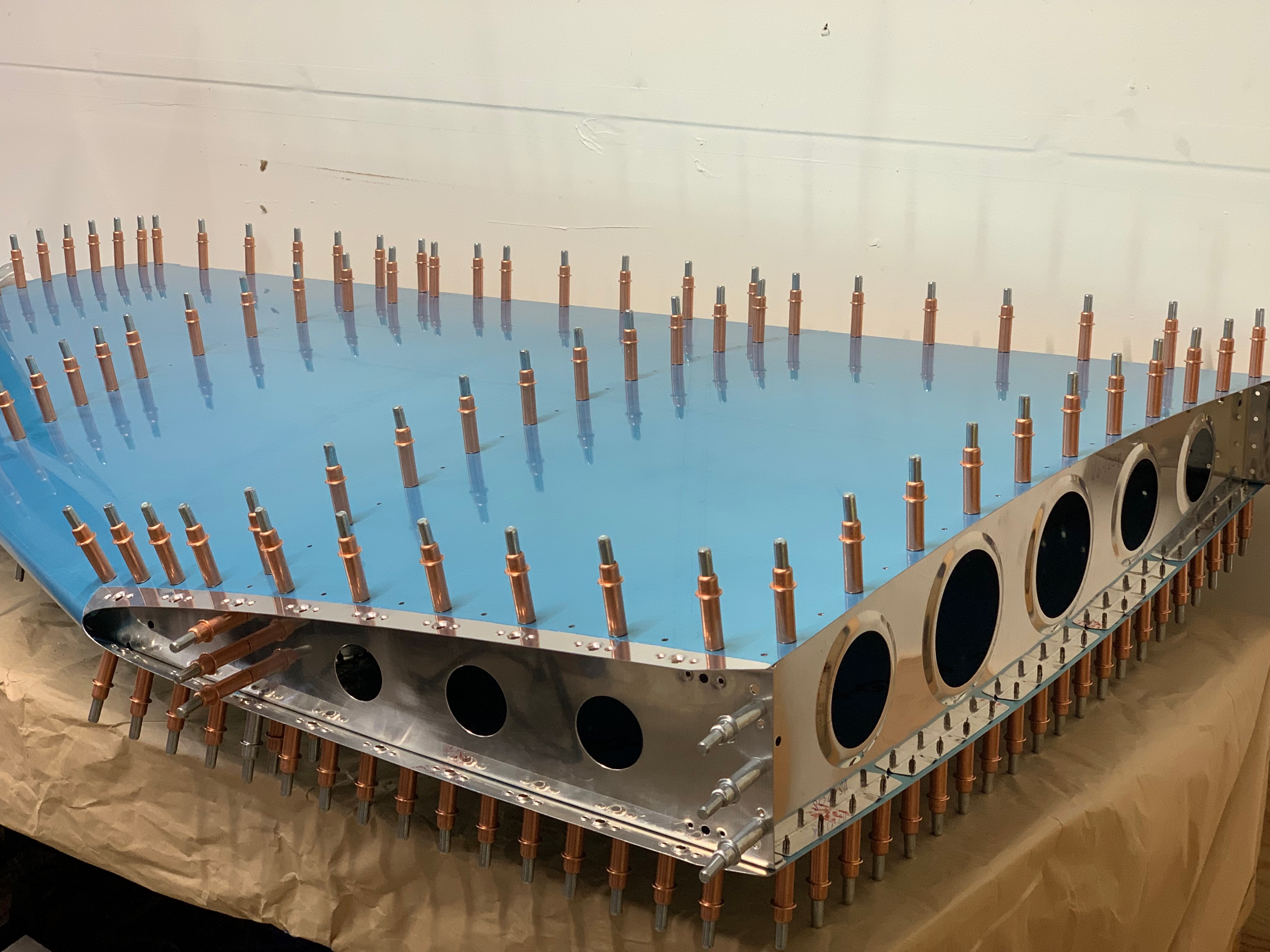
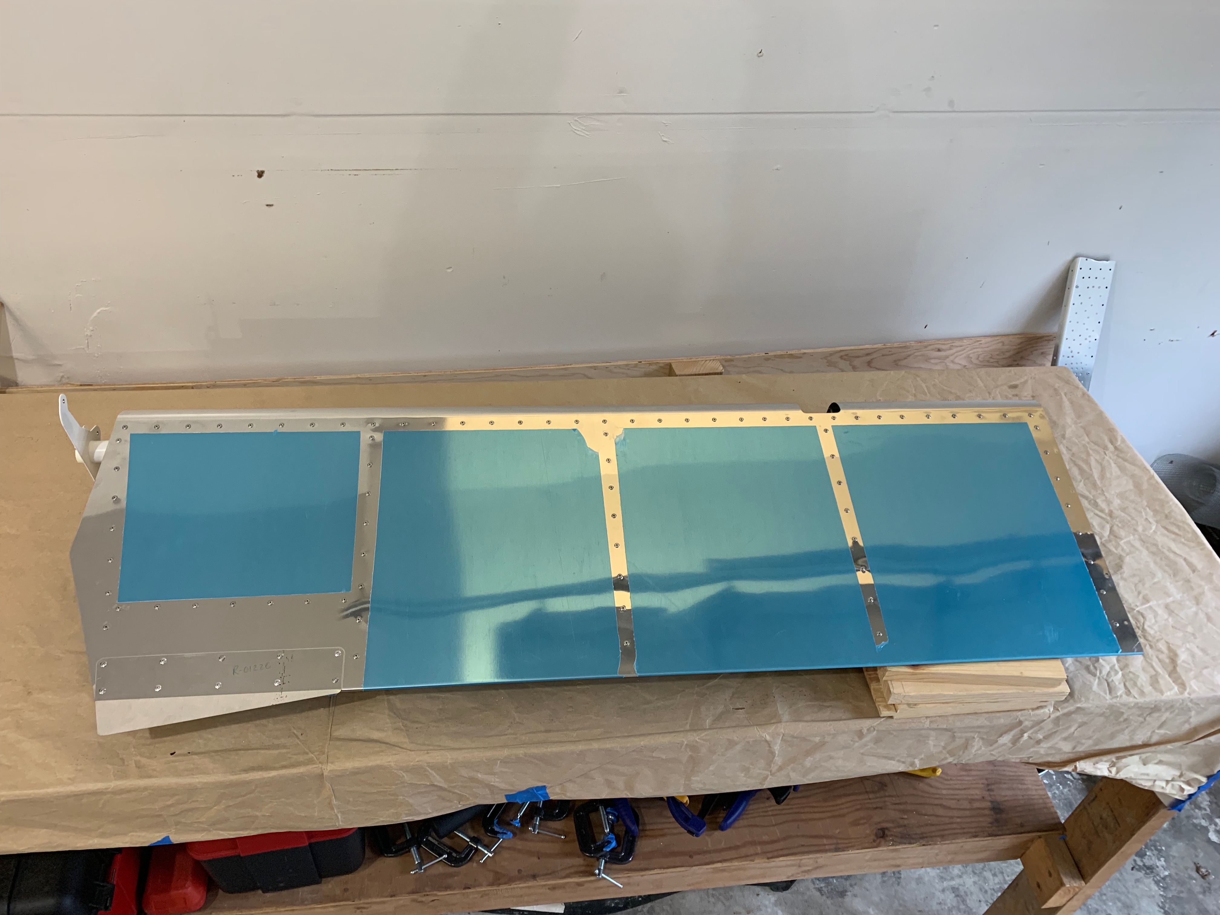
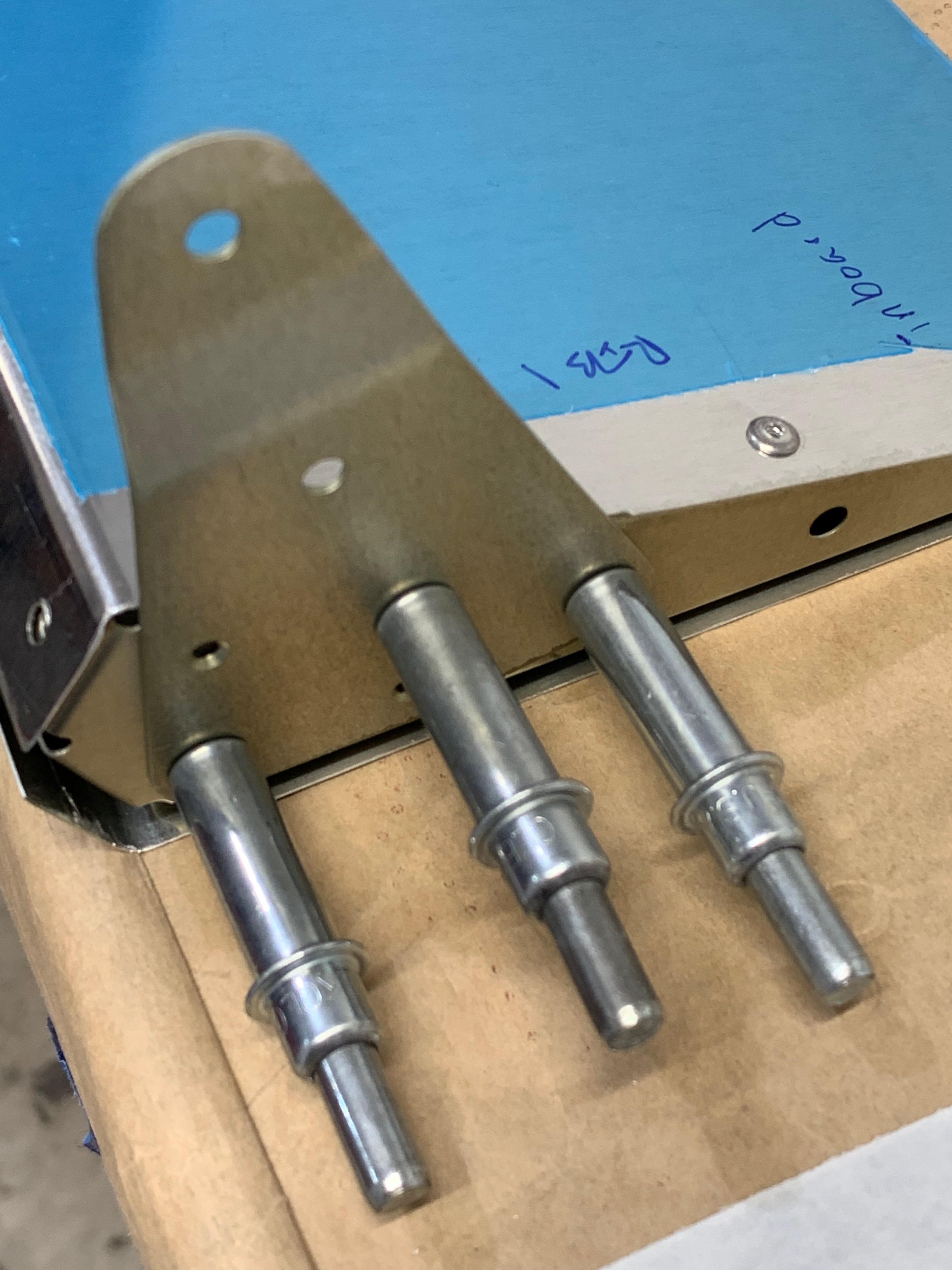
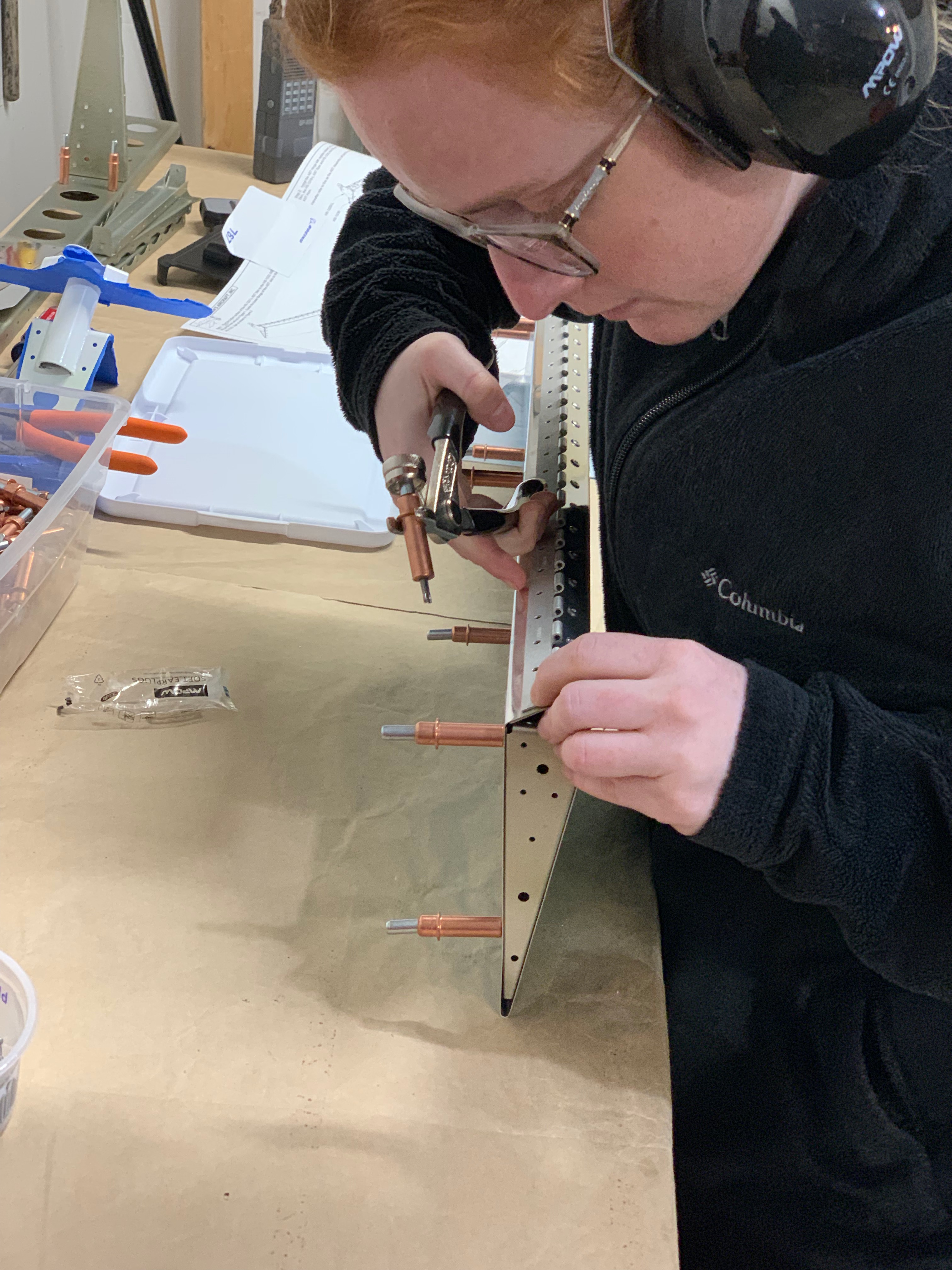
Below is the (primed) spar box Cleco’d together for match drilling of the Stabilator control horns (the white powder-coated piece). An upper and lower control horn are eventually attached to the control cables that will deflect the stabilator. For completeness, some touch up priming was completed after match drilling of the spar box. I also had to clean up (sand and re-paint) some scratches on the control horn – I used a similar process to the re-work I had to do on the Rudder Control Horn (WD-1205).

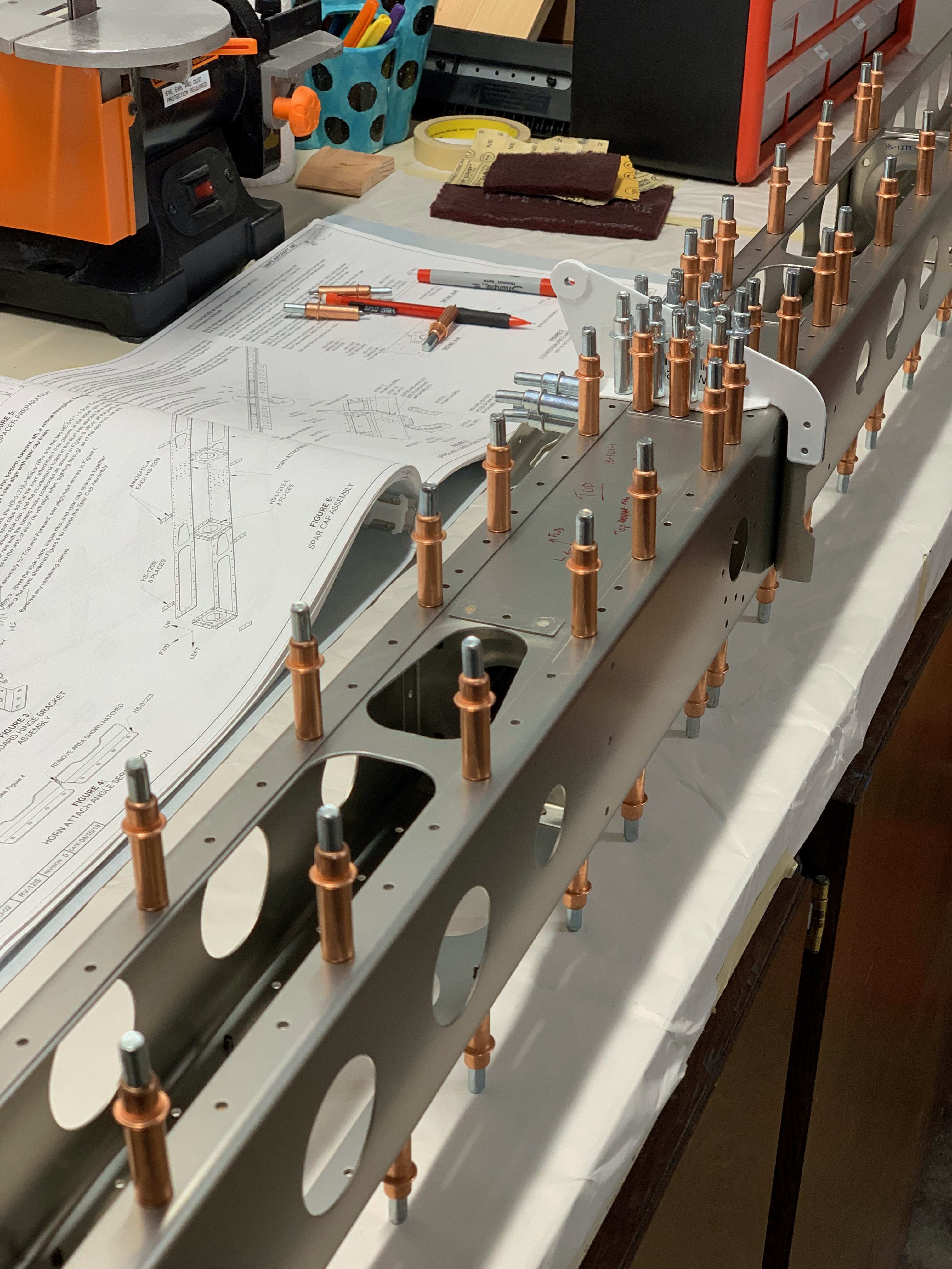
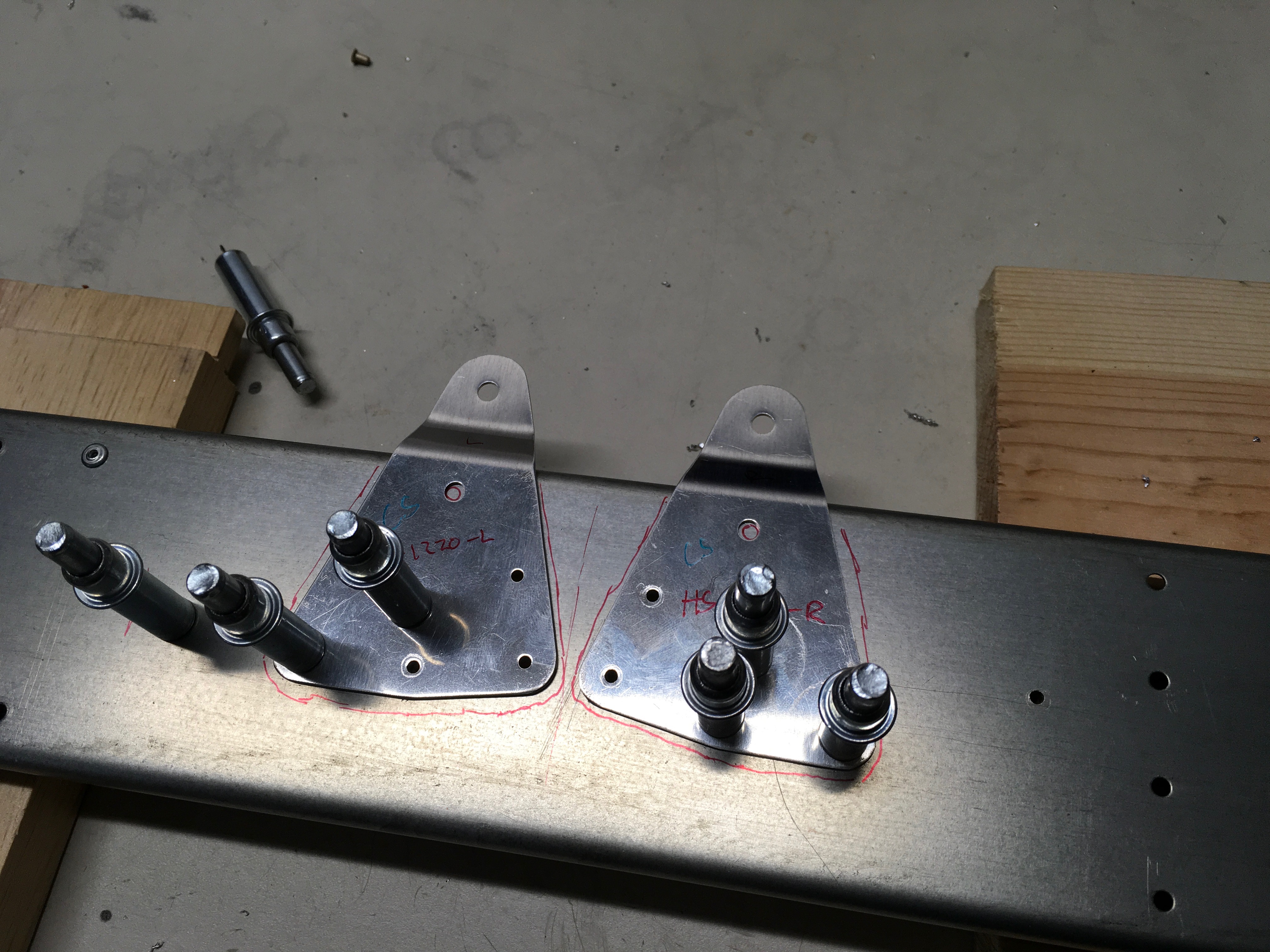
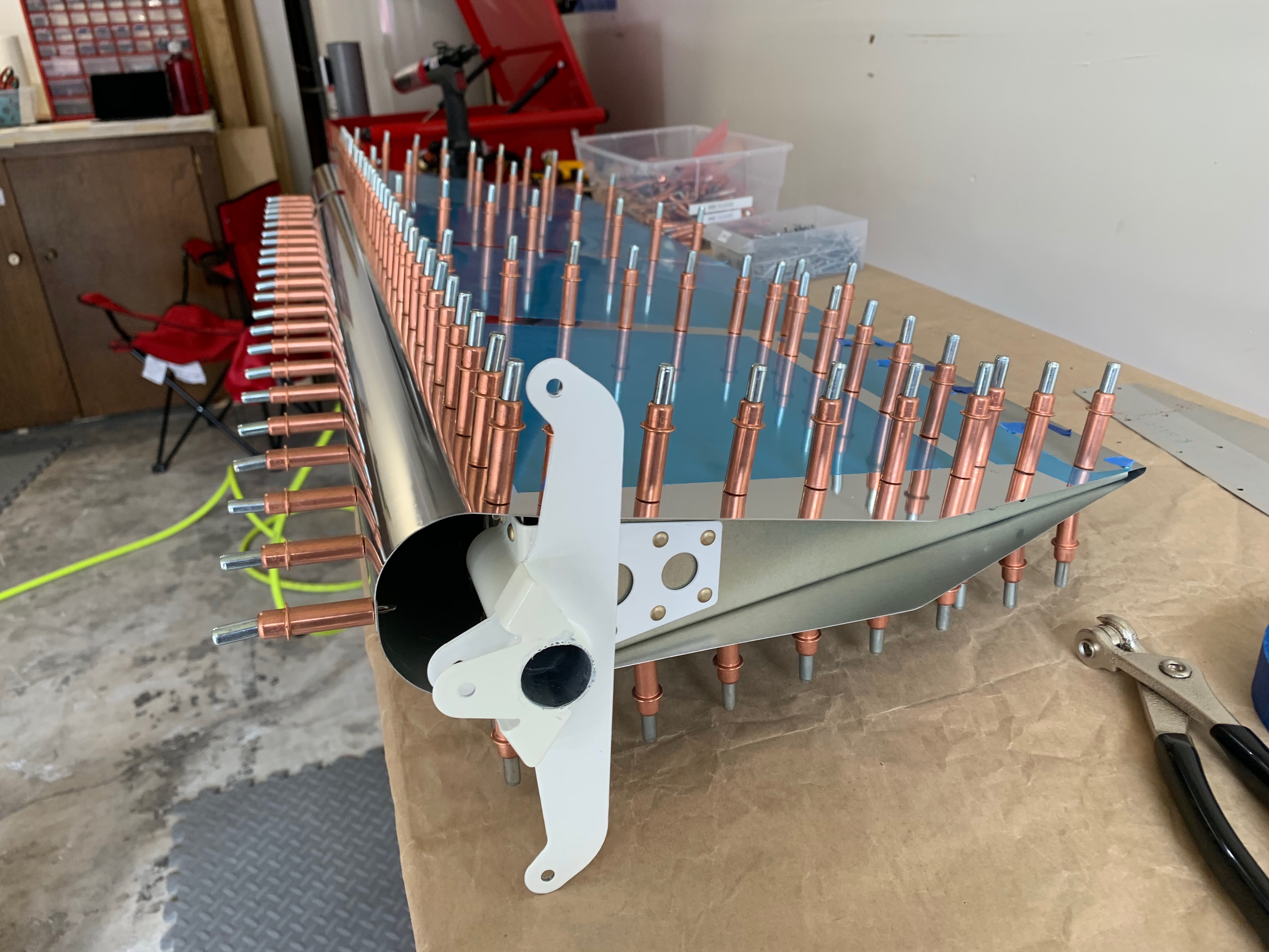
Once complete with the match drilling of control arms, there’s some additional match drilling for counterbalance bracket weldments that hold the counterbalance arm for the stabilator. The counterbalance arm extends forward for the stabilator into the tailcone; it provides moment that makes the stabilator assembly mass more balanced about its center of rotation.

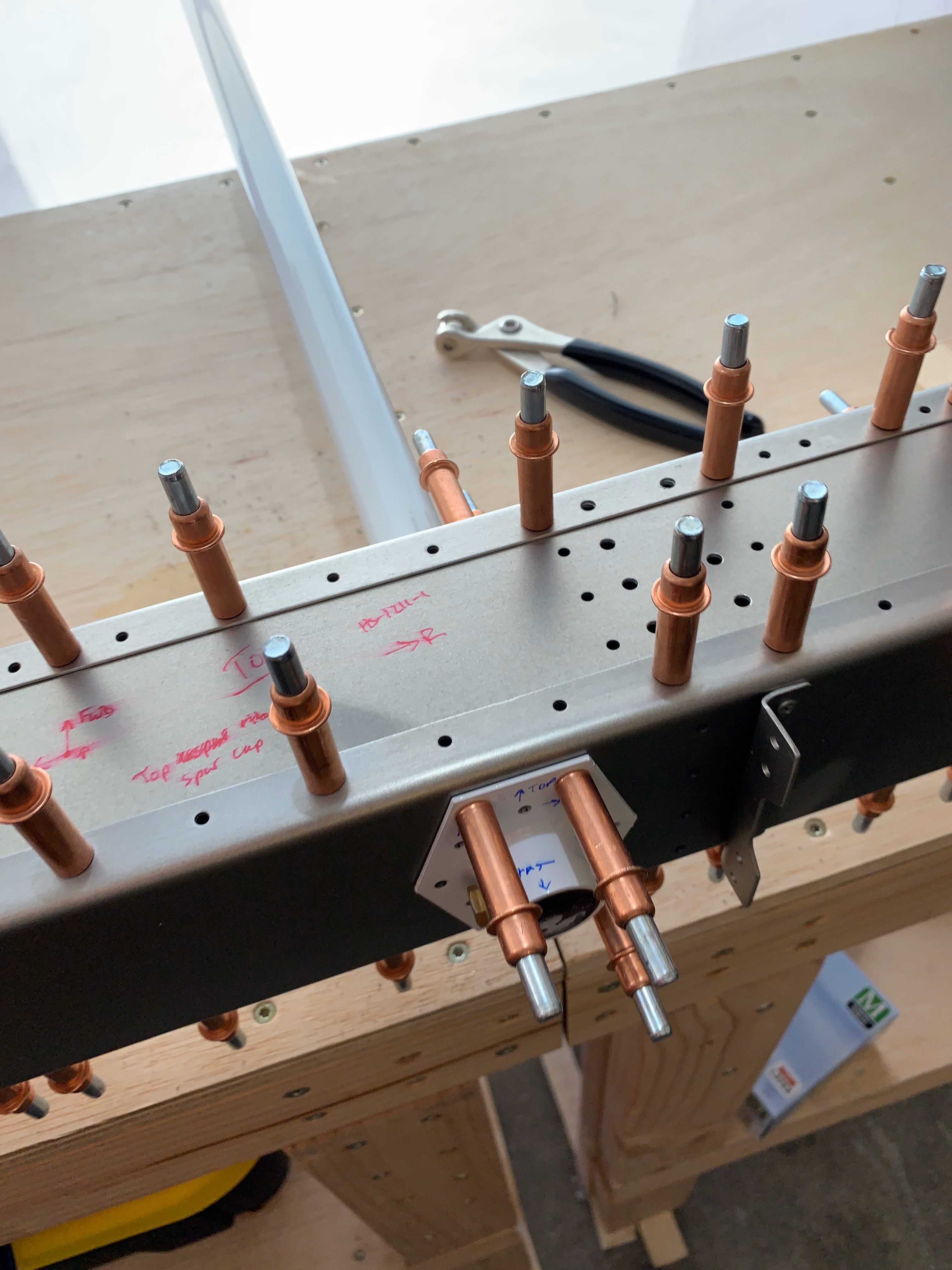
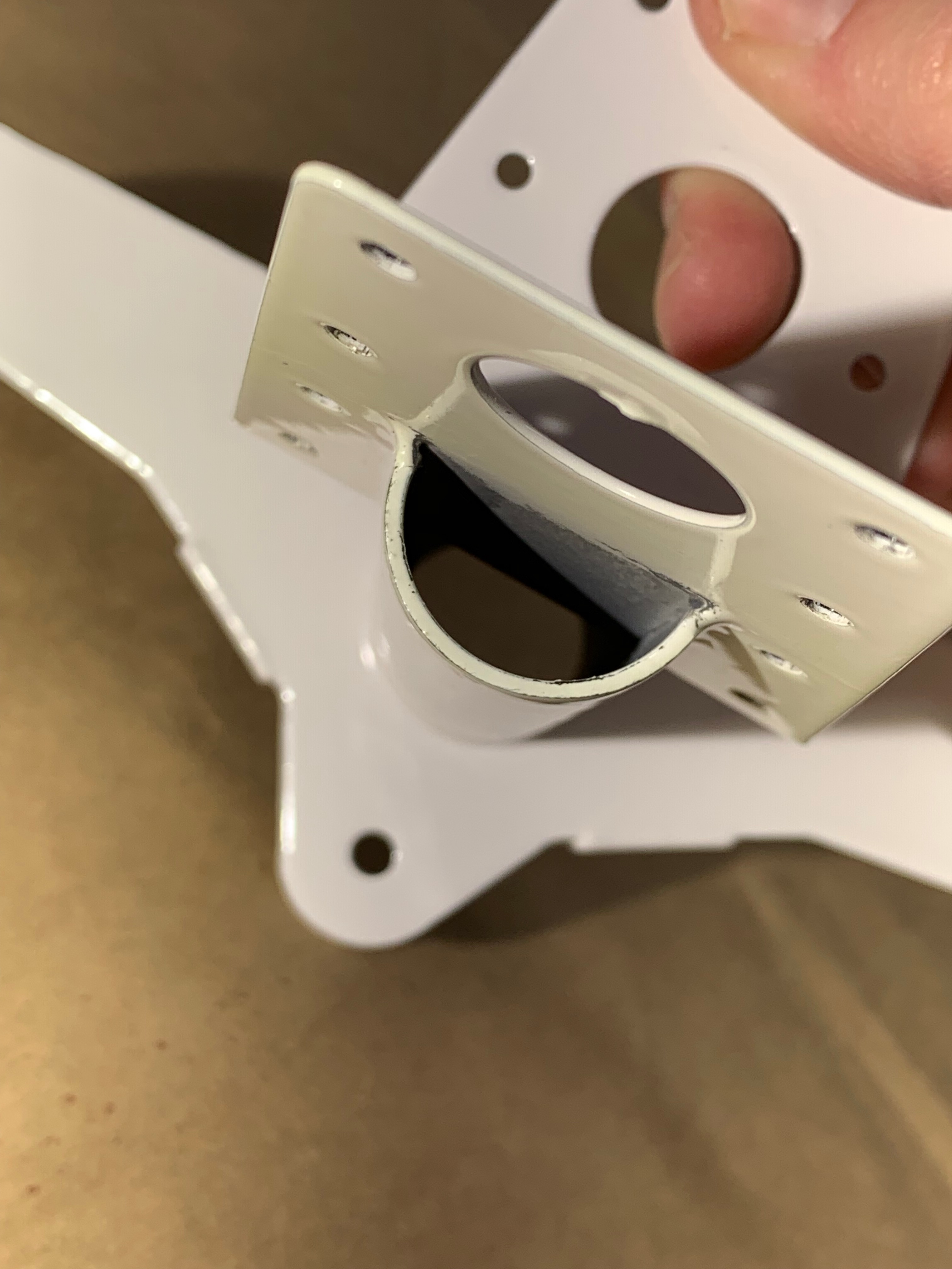
To keep the counterbalance arm from rotating, a bolt is passed through the white brackets on either side of the spar box. The holes from the brackets are match-drilled into the counterbalance arm, and a bolt is inserted through the assembly.

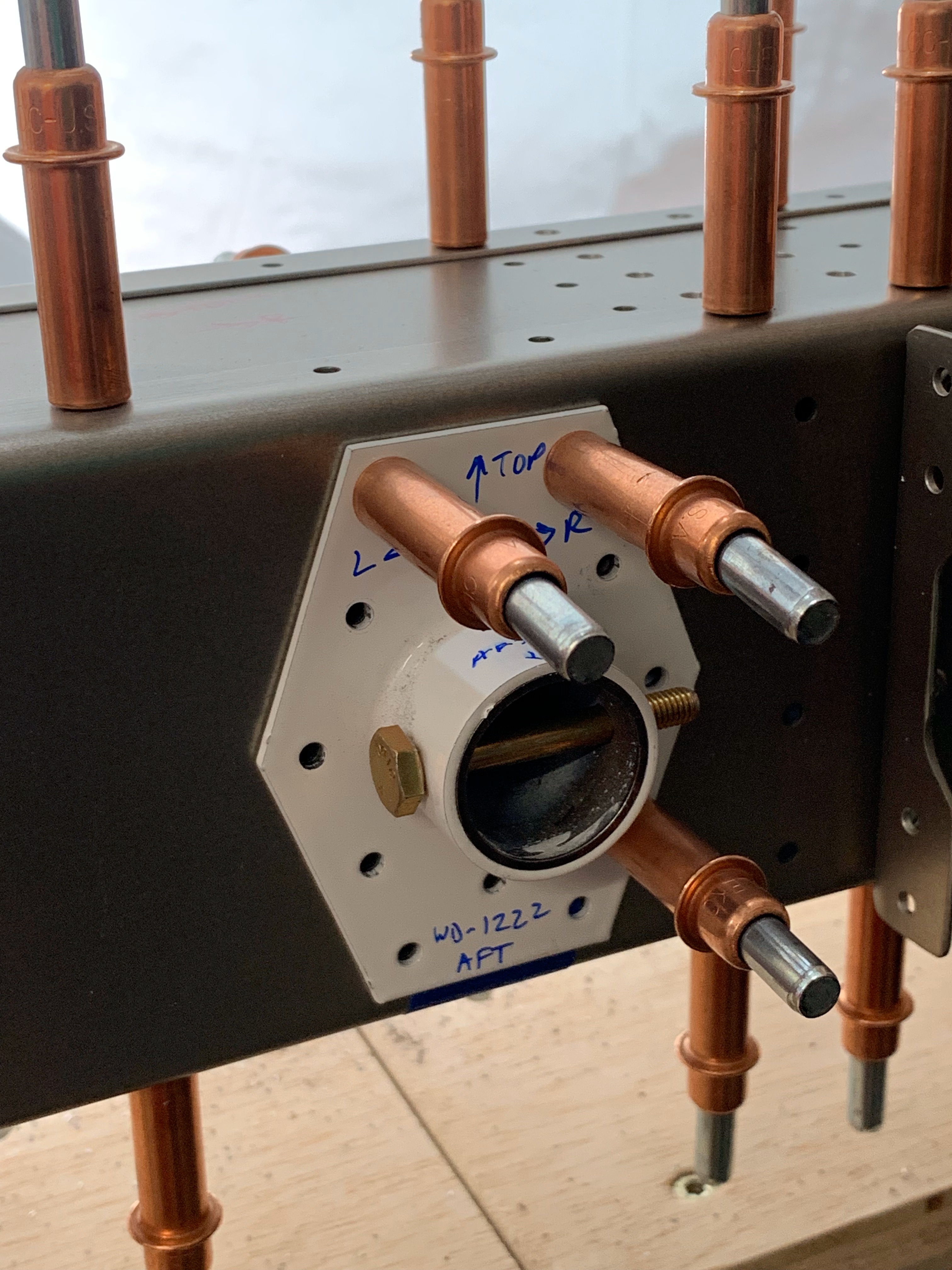
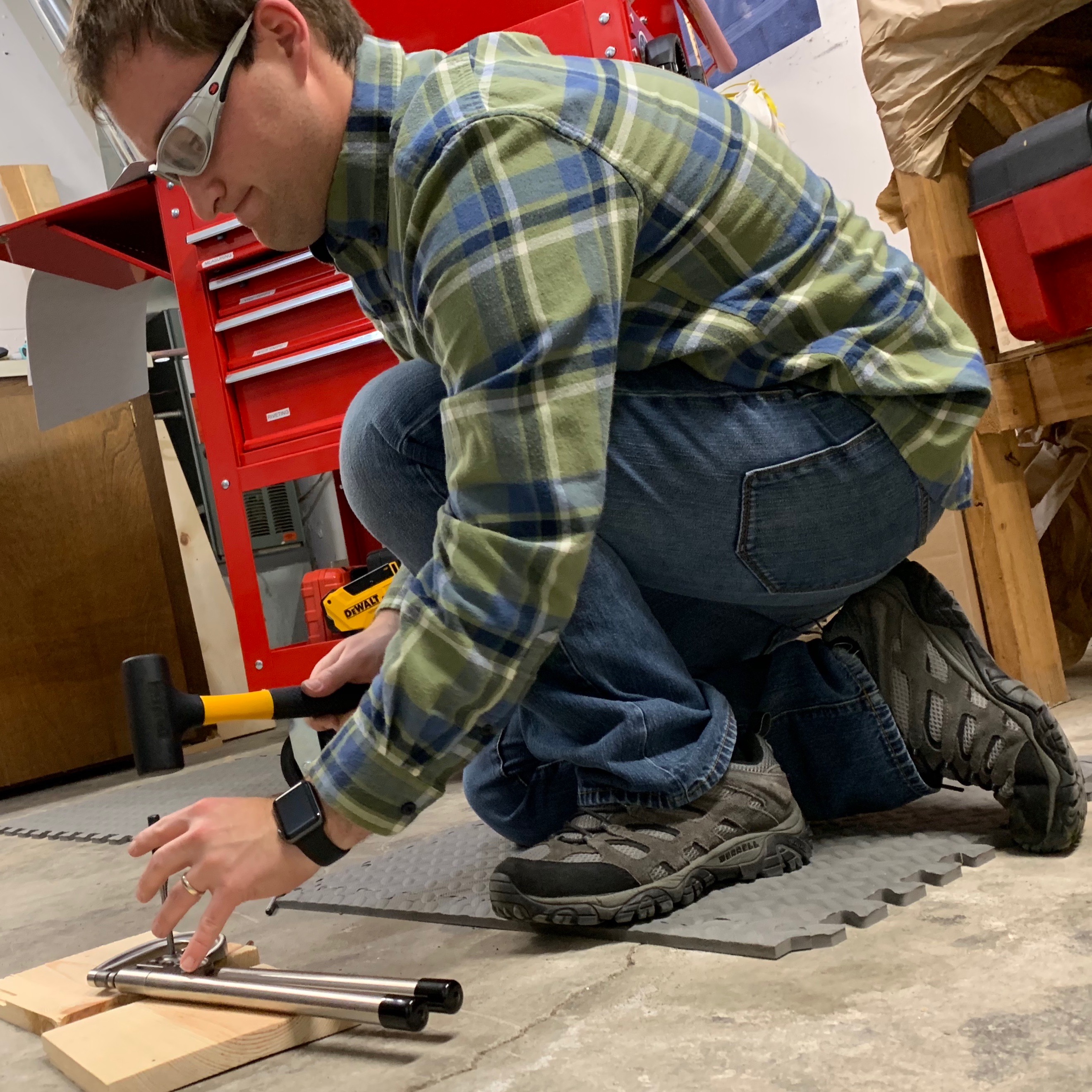
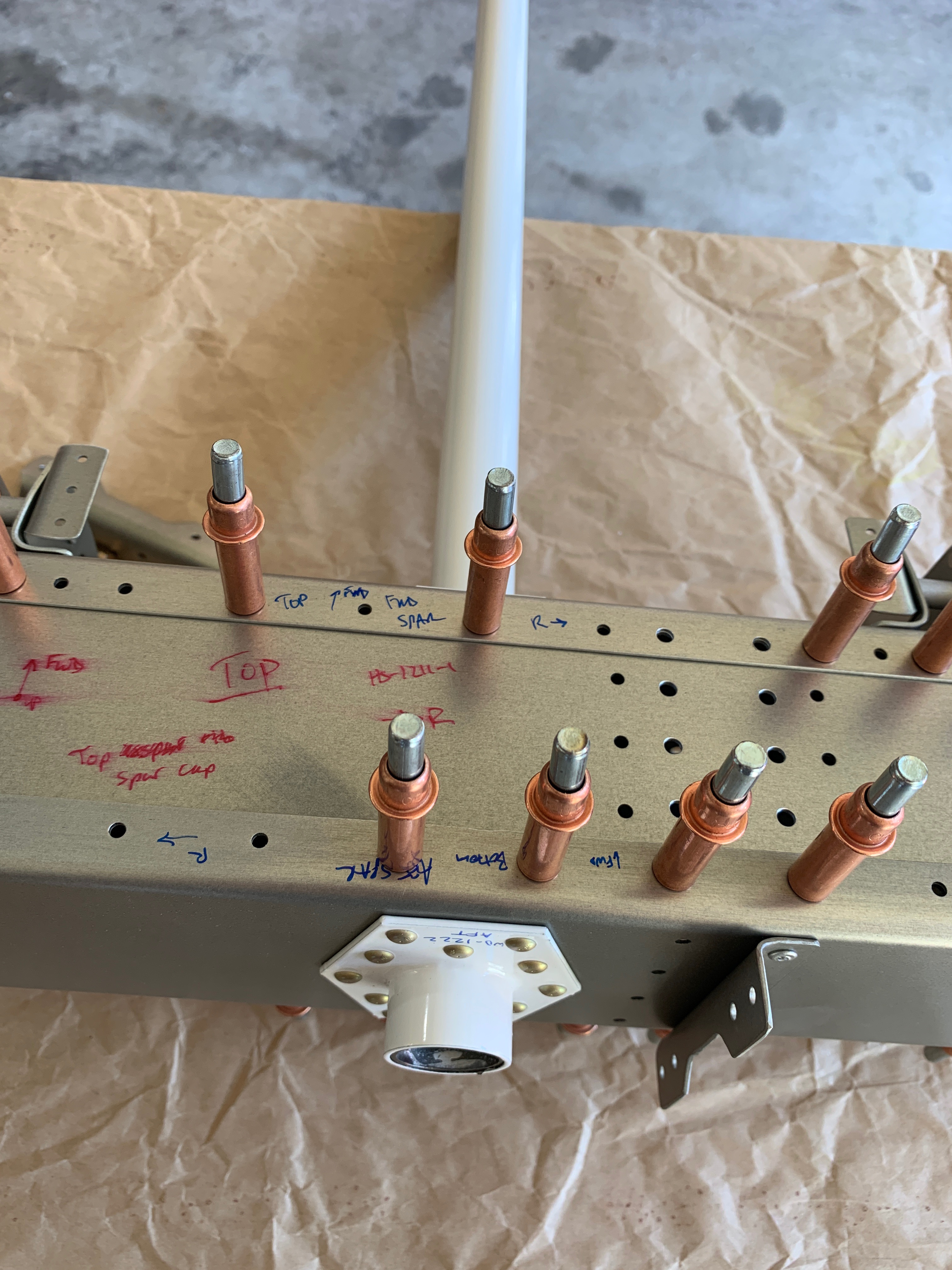
Would you believe that it is extremely important to mark these parts so that you re-assemble them properly? Van’s explicitly states this in the plans, but I found a way to screw that up. I actually fully riveted the brackets to the spar box, re-cleco’d things together, and then eventually realized that I had a bracket 180˚ rotated from the correct installation. Needless to say, I got some practice drilling out the rivets using a rivet removal tool. Somehow I got extremely lucky and was able to remove all of the rivets without issue, without enlarging holes beyond the spec, and without ordering new parts! Beginners luck!

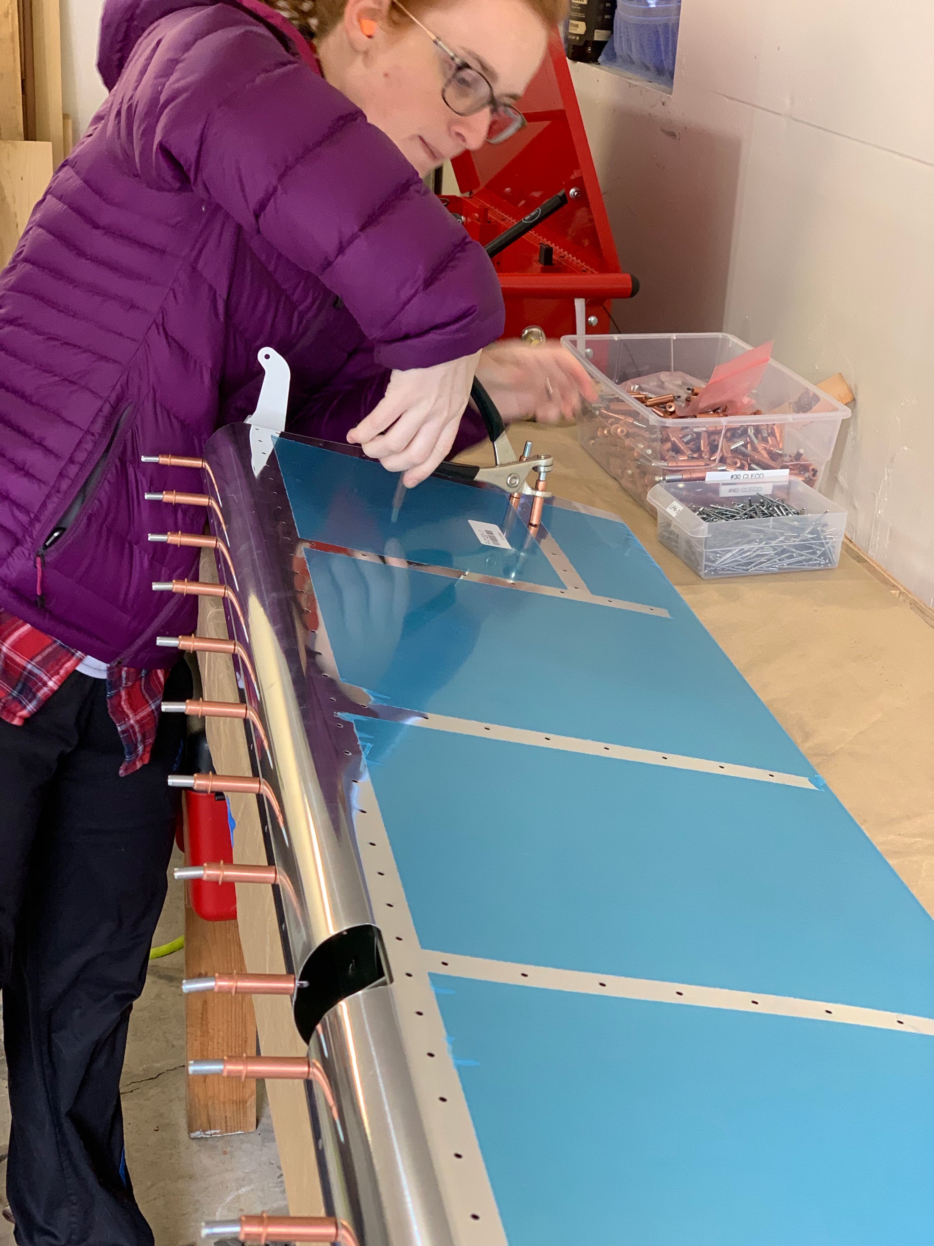
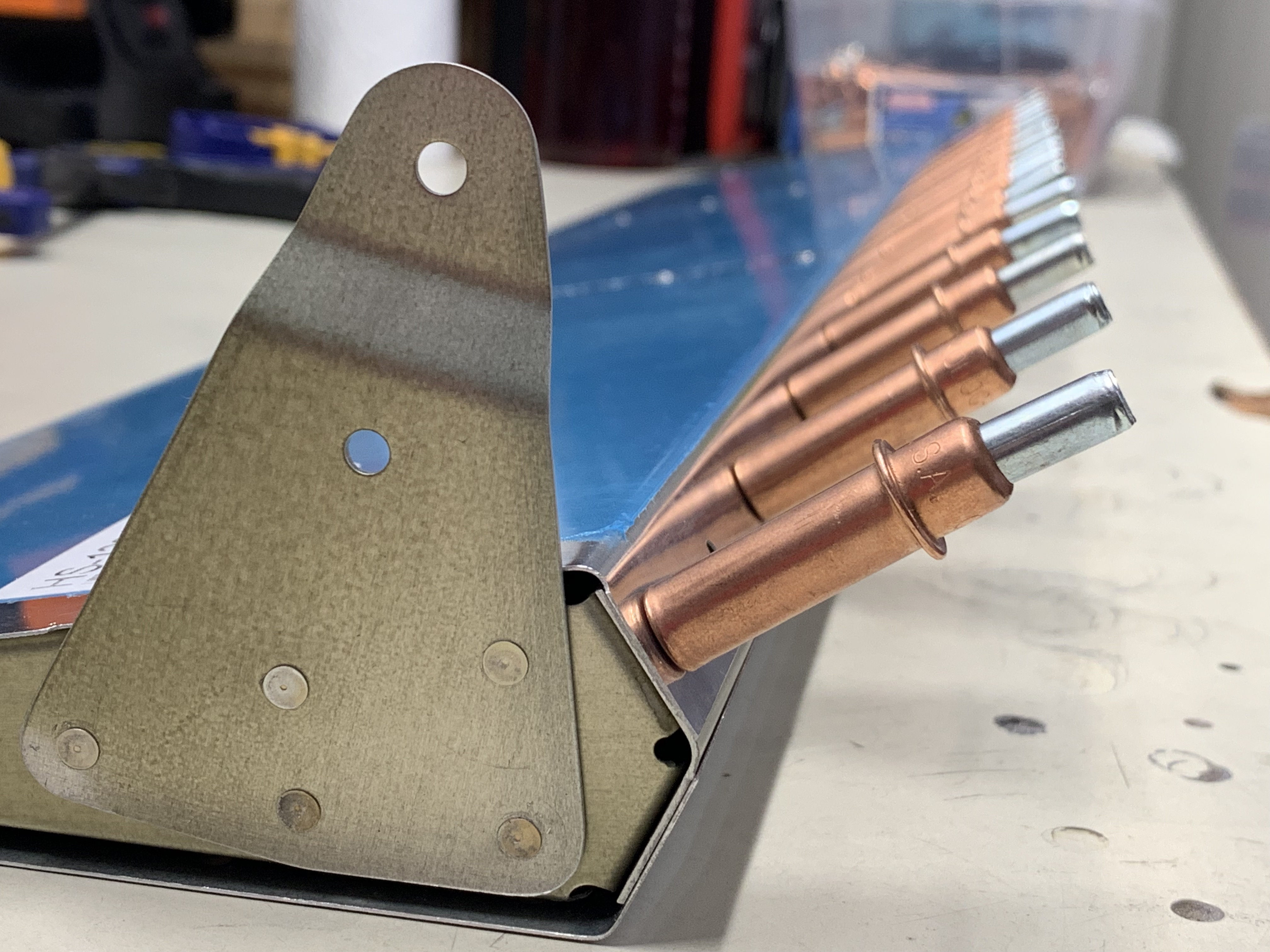
And hey, here are those new work tables that the parents helped us construct in April! This is just before permanently installing the cleco’d hinge bracket assemblies.

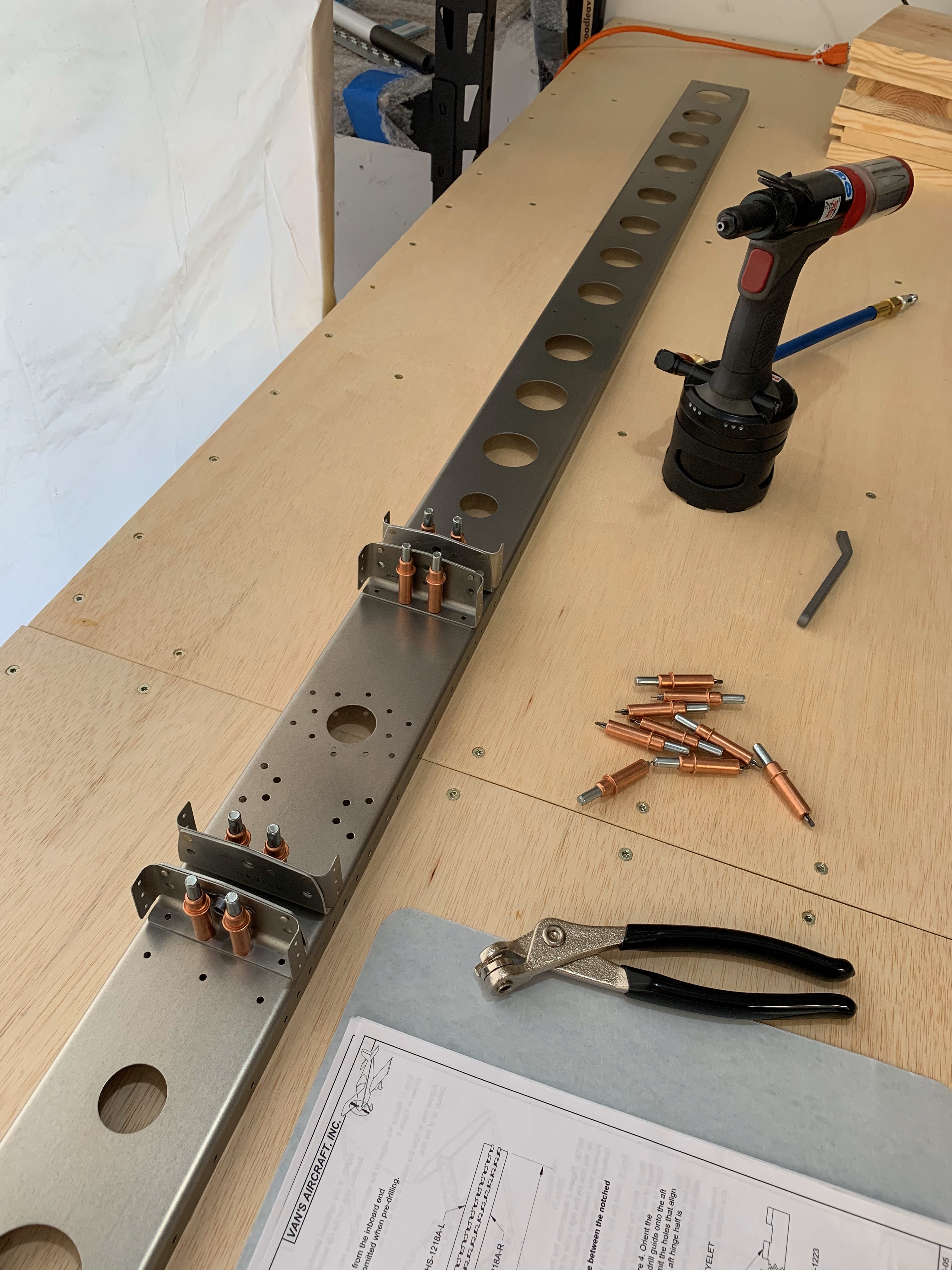
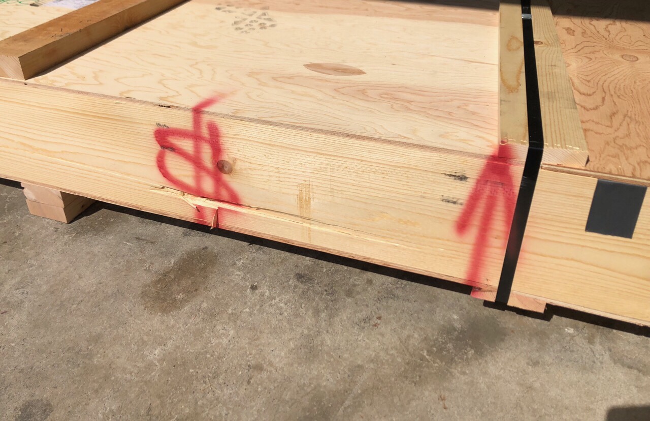
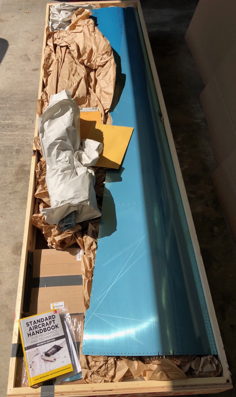
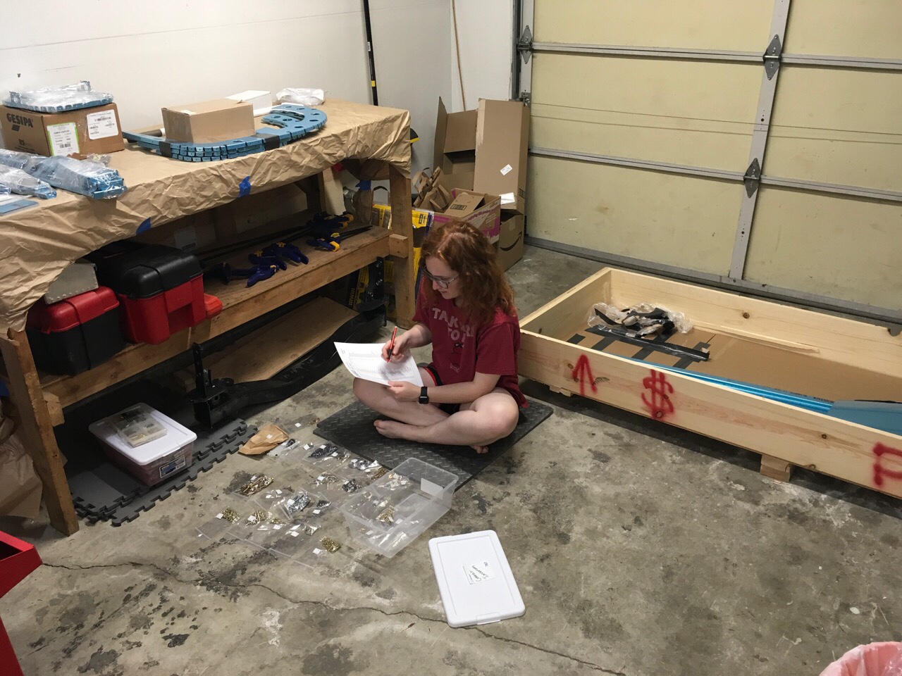
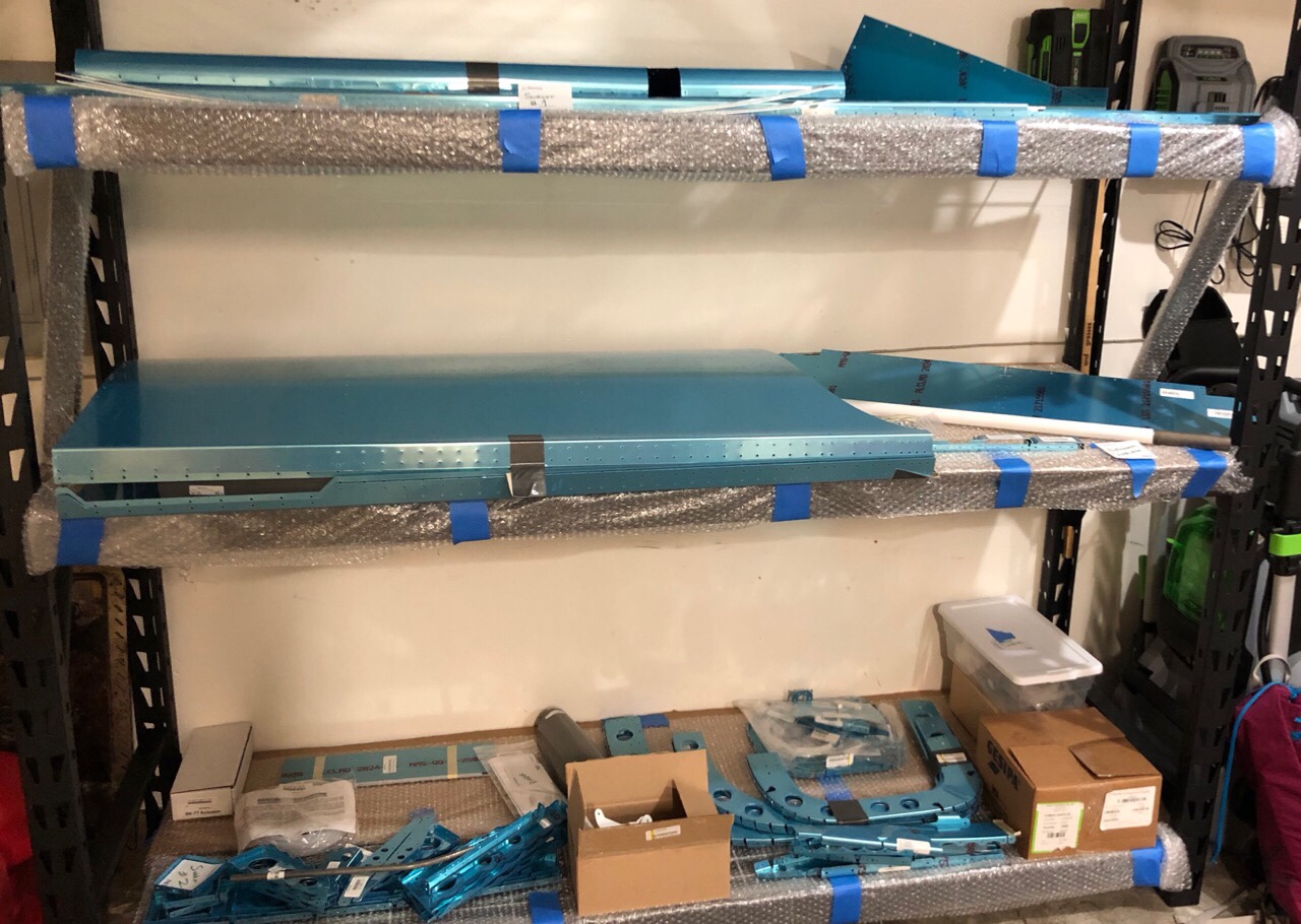
May 2019 saw relatively little progress in the build other than the wing kit arrival and inventory. Kelsey and I were too busy enjoying our anniversary trip in Utah/Arizona! I even convinced her to start building an airplane with me before 5 years of marriage:

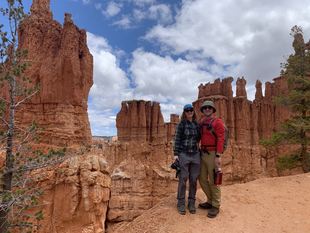
Fast-forward to June – Mom and Dad returned to the Pacific Northwest and this time I was determined to put them to work on actual airplane parts. Mom did hours of deburring for Stabilator ribs, and I got dad to work on some final assembly of the Stabilator spar box with me.


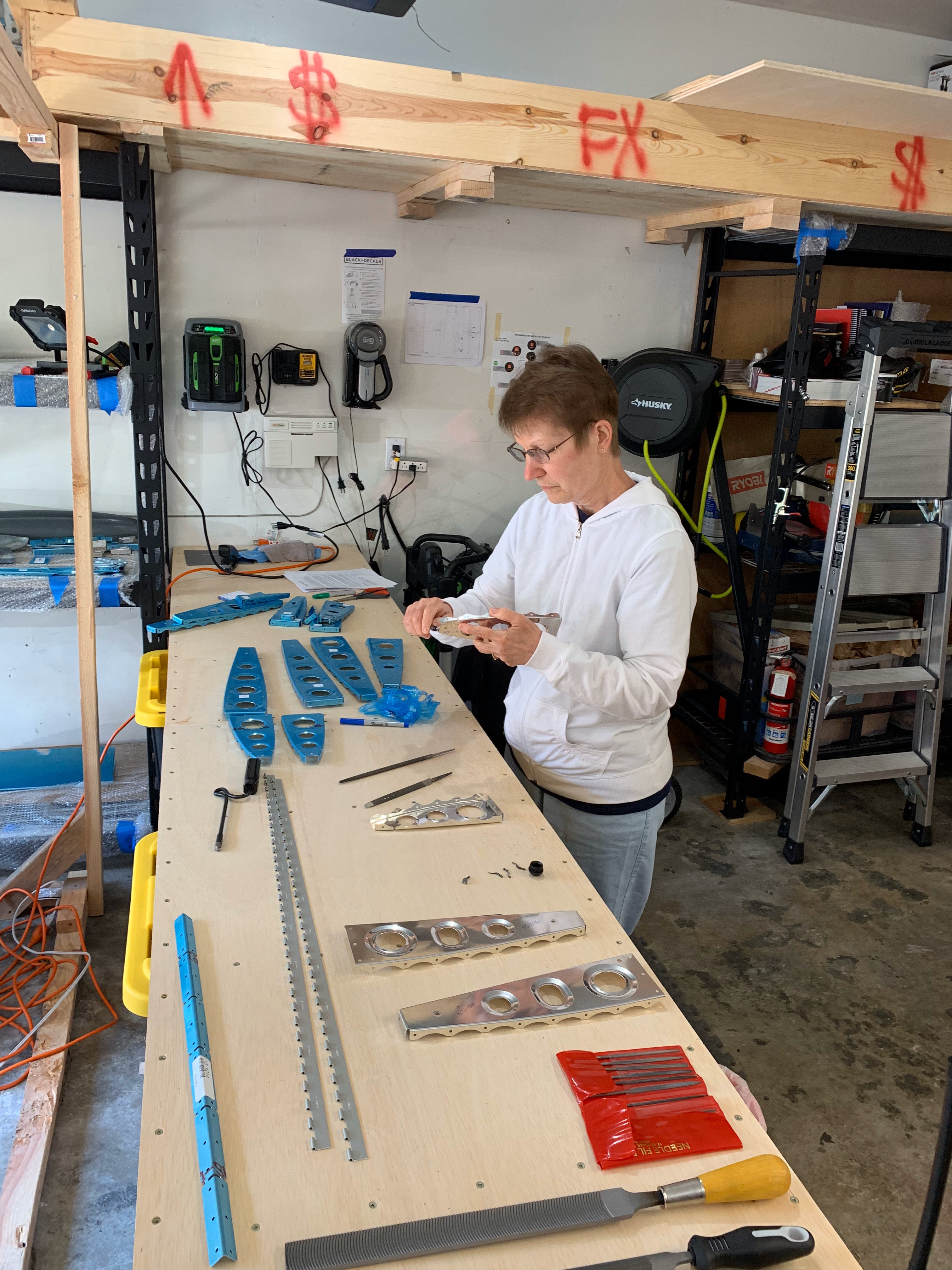
The re-work I was mentioning before? Yeah, this was about the time I discovered that the counterbalance bracket was upside down. Drilled those 12 solid rivets out and re-riveted it on after rotating it 180˚.

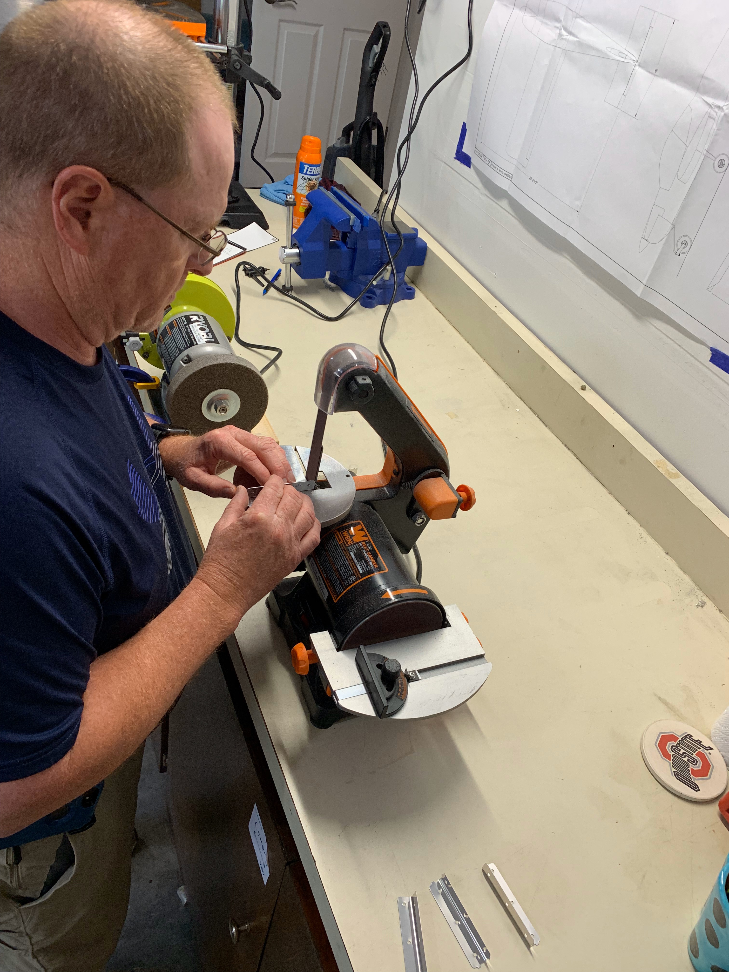
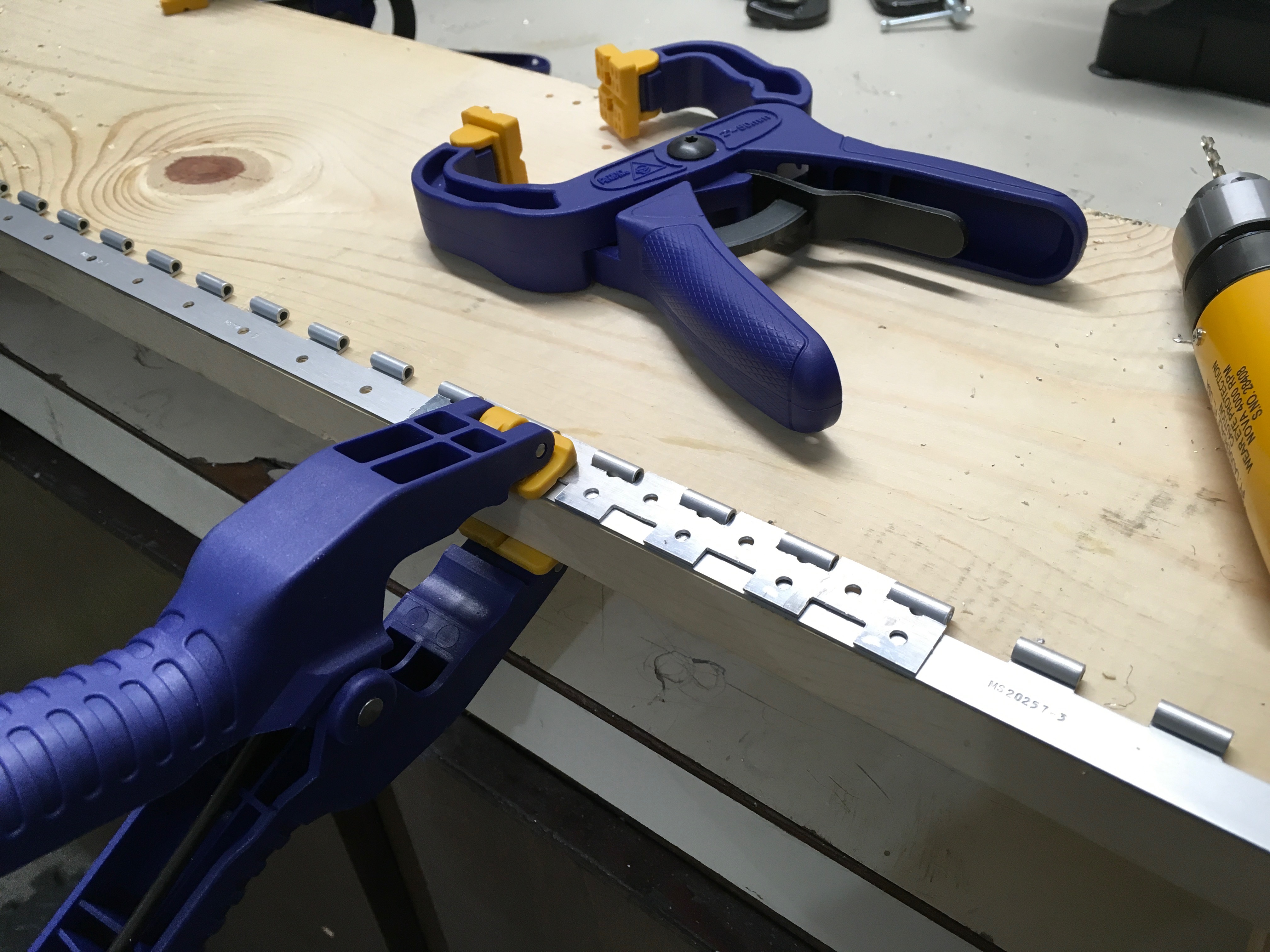
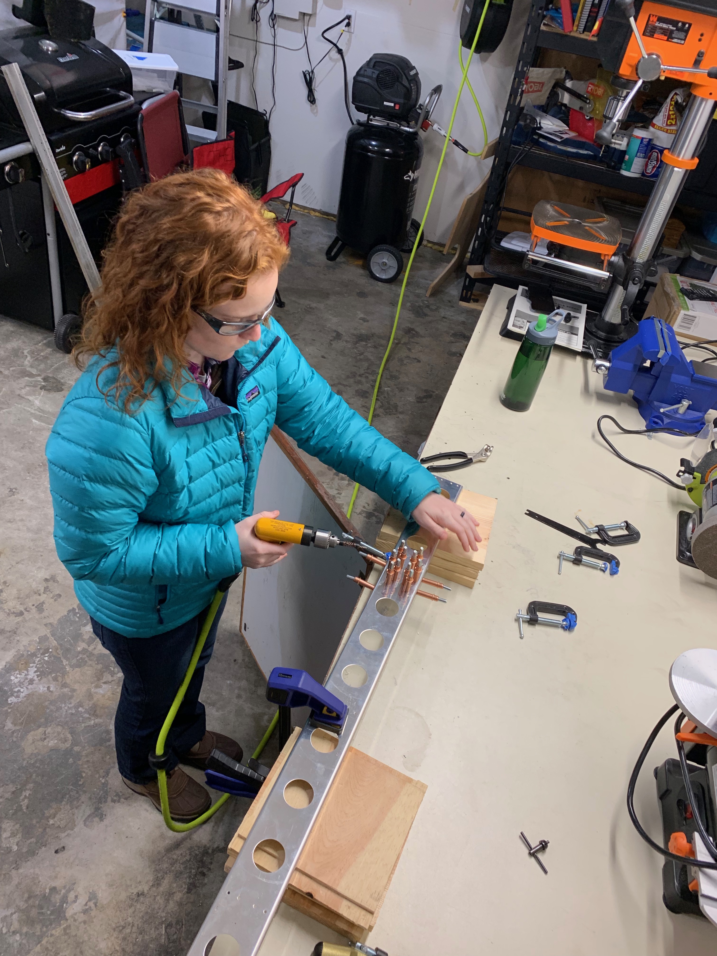
Cleaning up some rib clips! These attach to the spar box; the Stabilator ribs will be riveted to them later on.

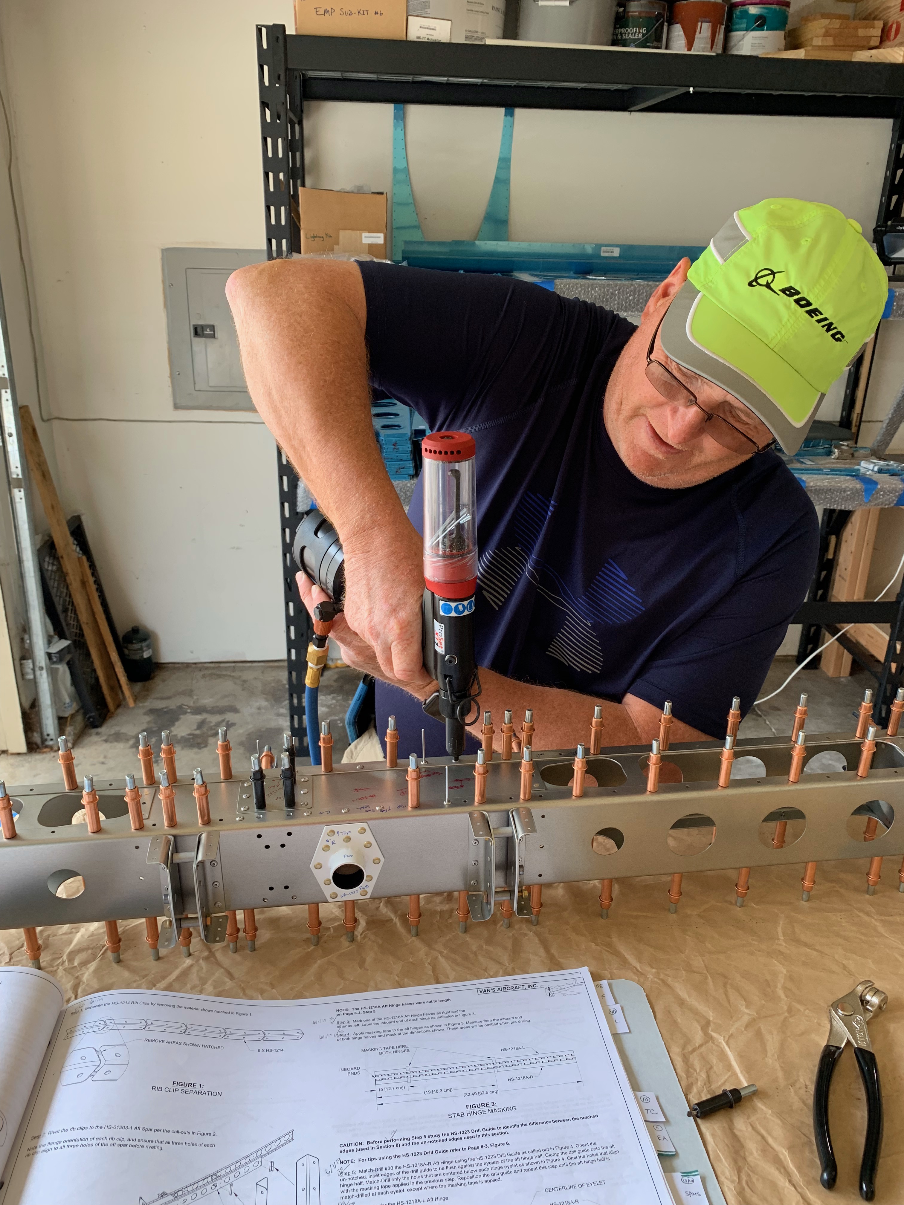
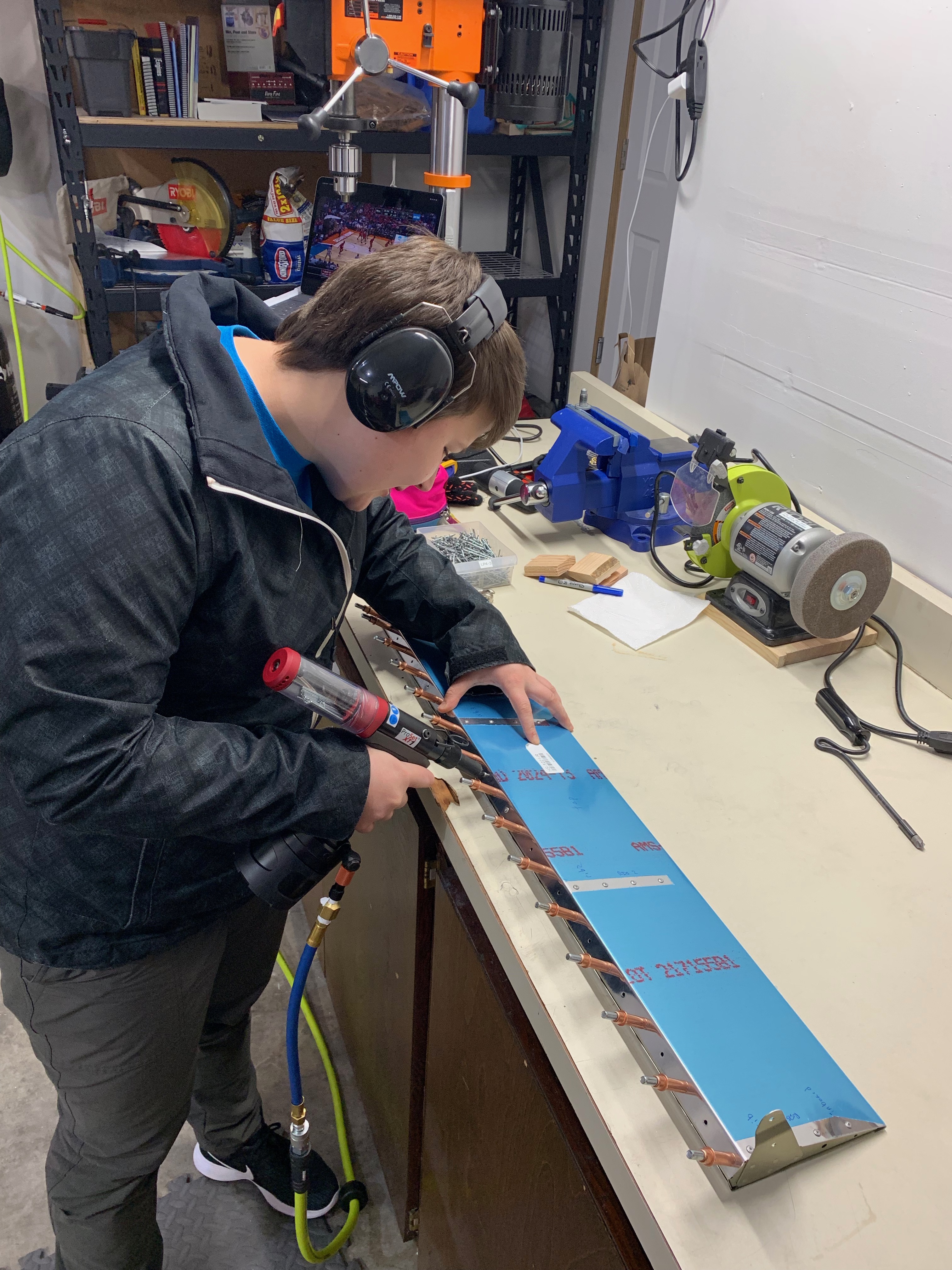
Woohoo! Mom and dad pulled their first rivets on the airframe. We all worked together to rivet the stabilator spar box and control horns. When we finally get to fly, they can say with confidence that they helped us build! 🙂

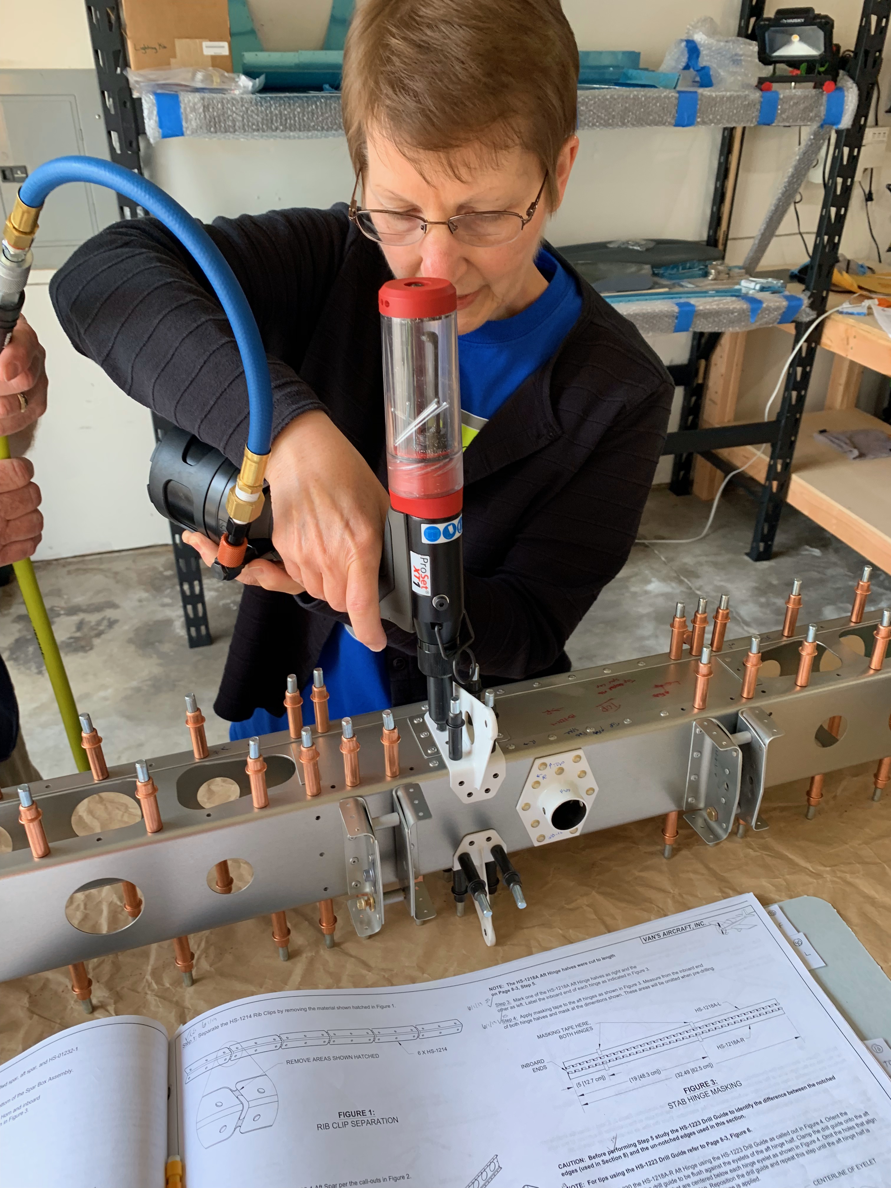
I thoroughly enjoyed getting some more family involved in working on the plane – and highly recommend it for any builders out there wanting to share the fun.

Unfortunately, after the family visit ended, I got really busy at work and lost momentum again. I didn’t even touch the parts again until nearly September!

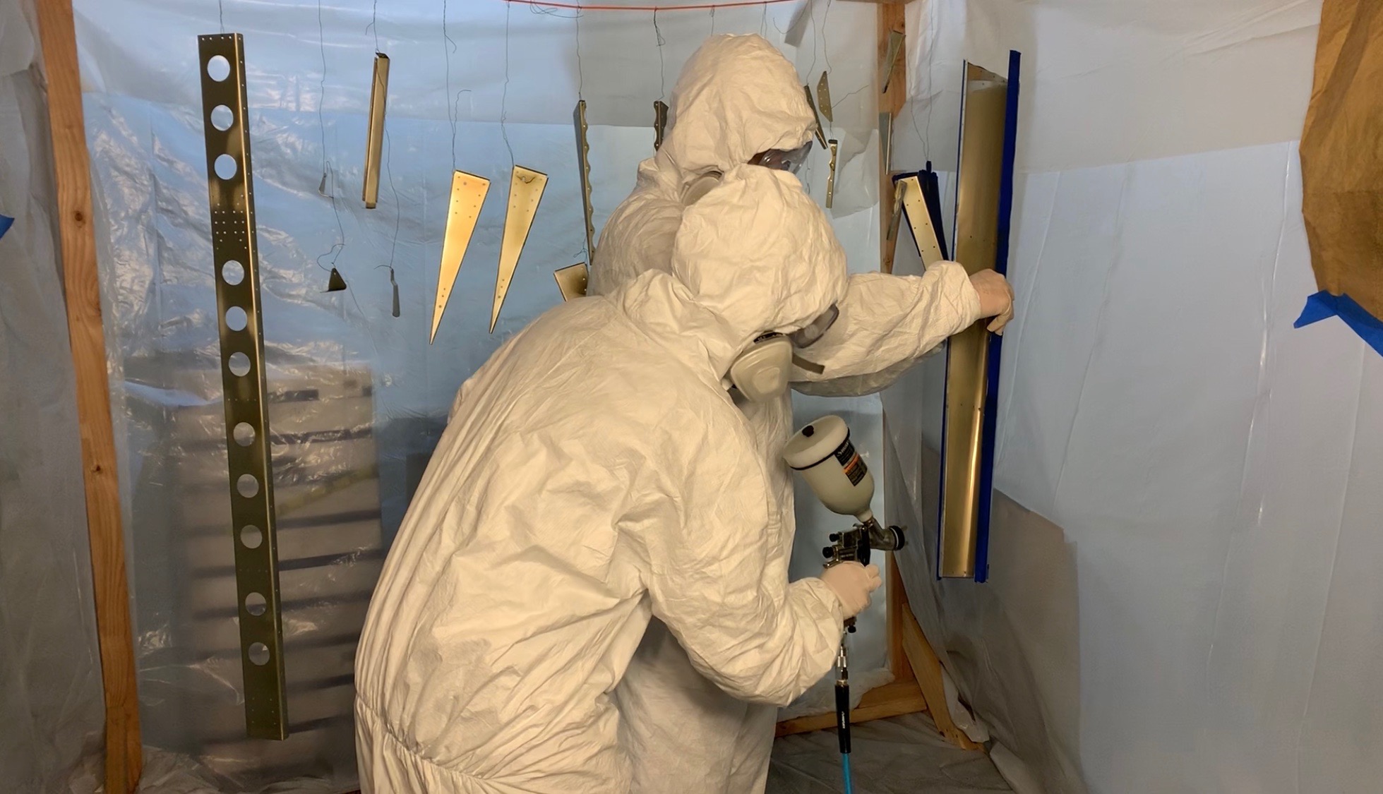
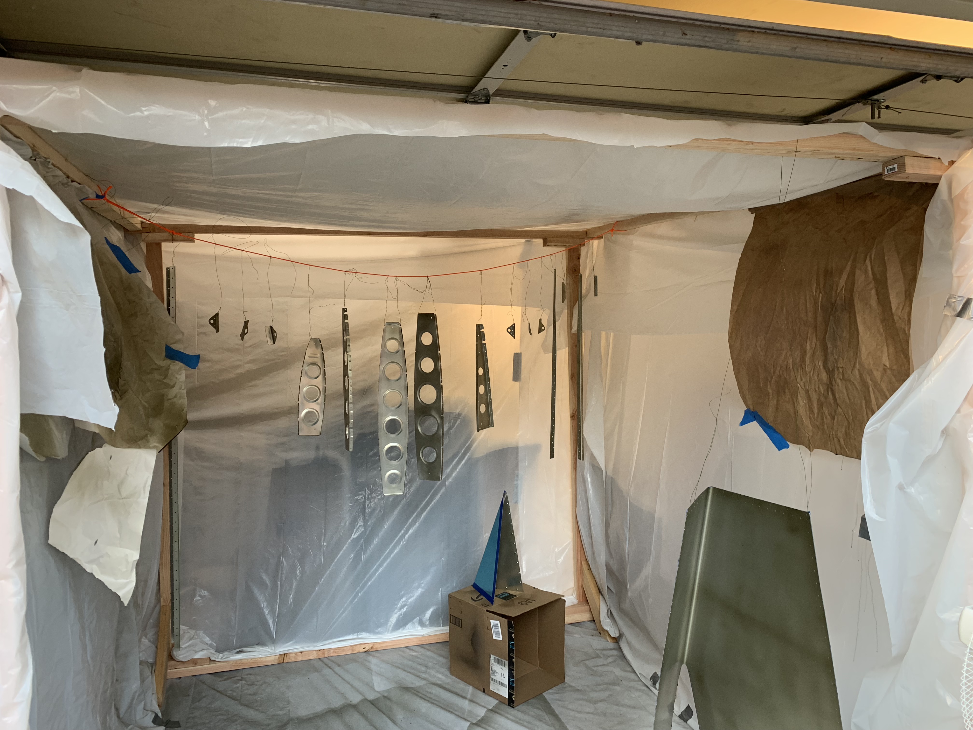
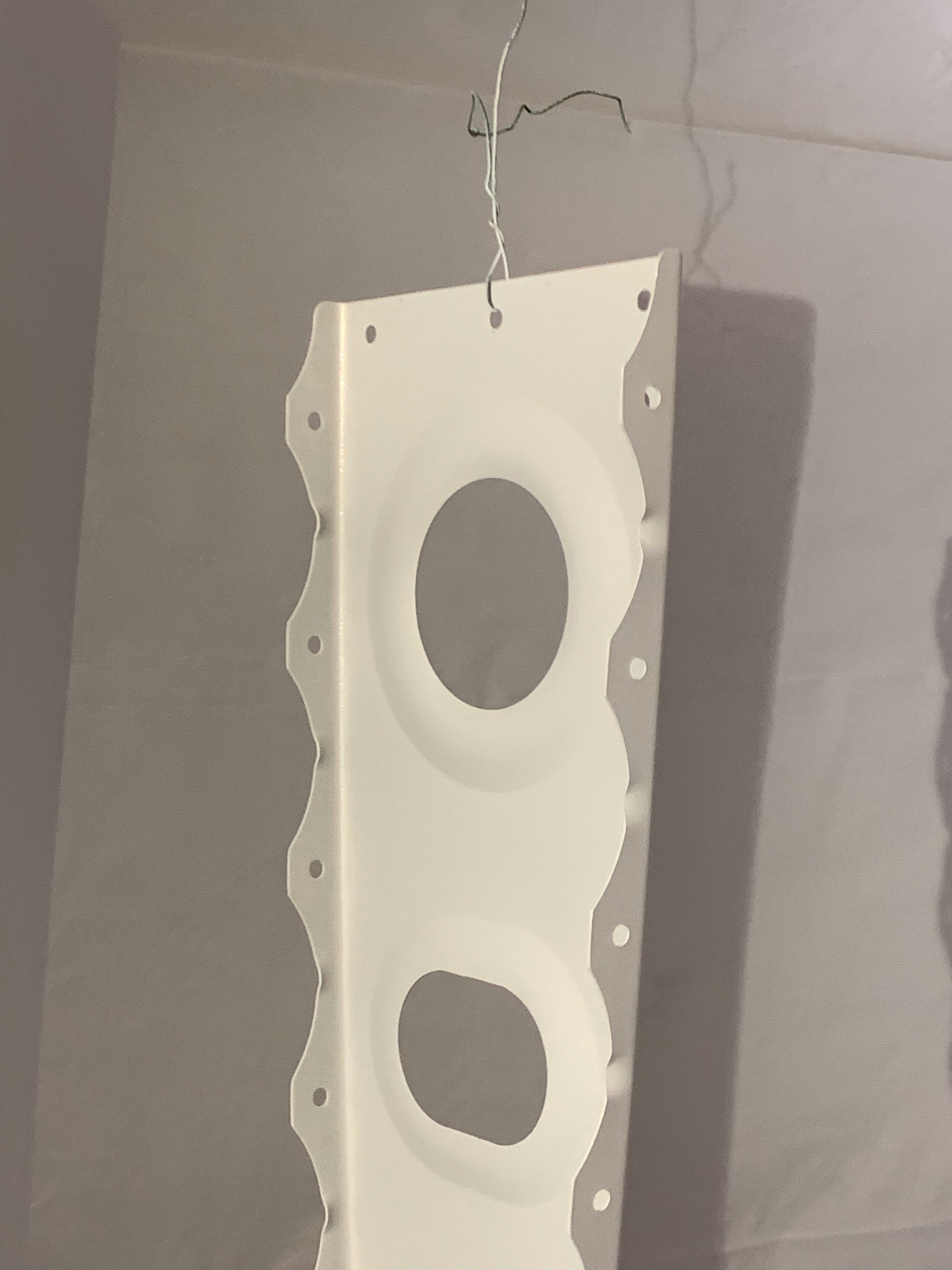
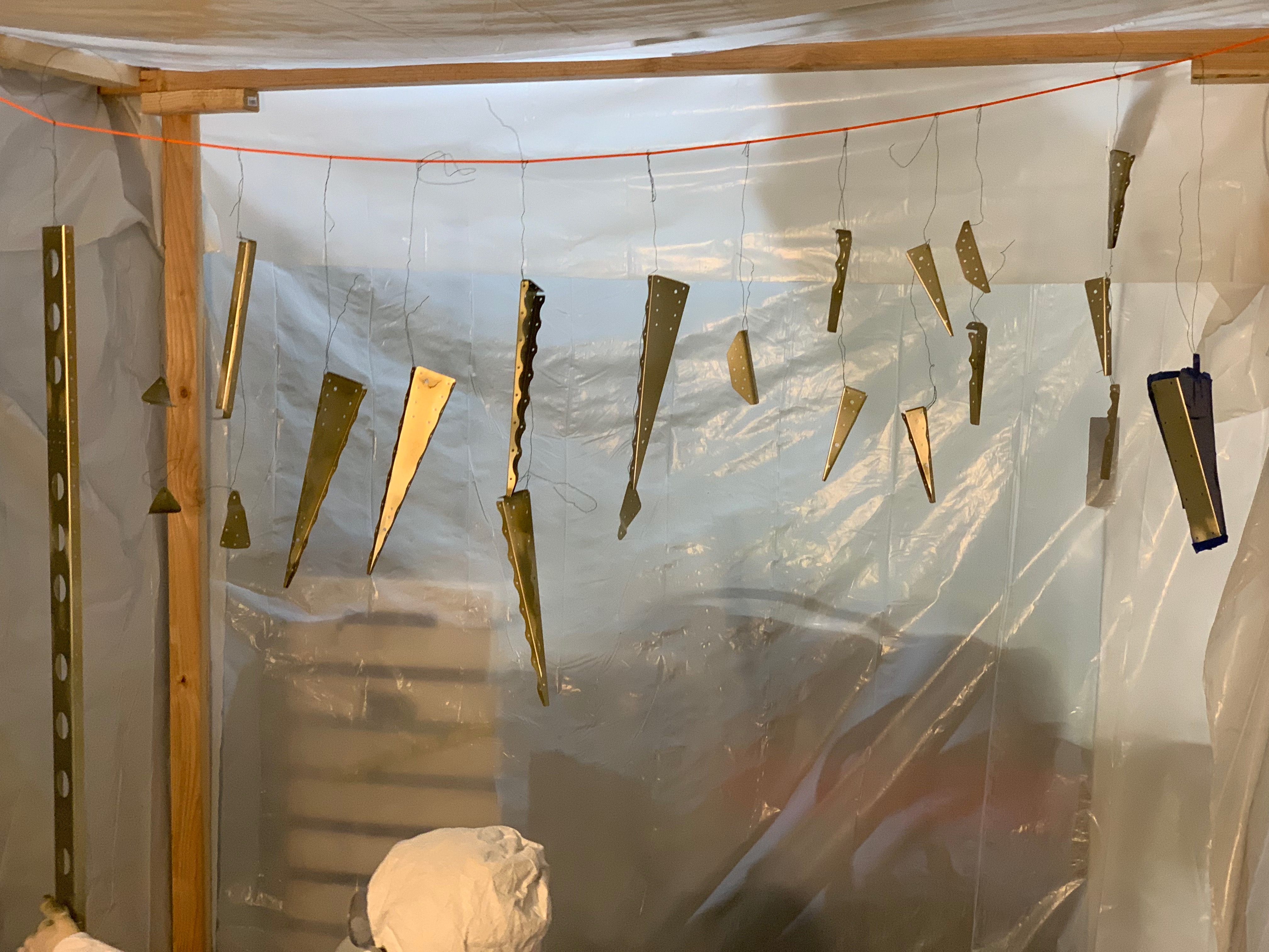
After the many hours mom put in to deburr stabilator ribs, Kelsey eventually got to flute (straighten) and prime them. This September 2019 was my first real experience priming parts with the Stewart Systems EkoPrime. I will admit that I practiced a little bit in a preceding batch on a friend’s RV-14 parts and the 6 rib clips for the stabilator. The process is quite a bit more involved, with extensive cleaning, mechanical/acid etching, spraying, drying, and finally priming the parts. However, this stuff is much less toxic than the two-part P60G2. I will plan to use it for the foreseeable future. (And again, will do a more detailed post later about the process and why we switched).


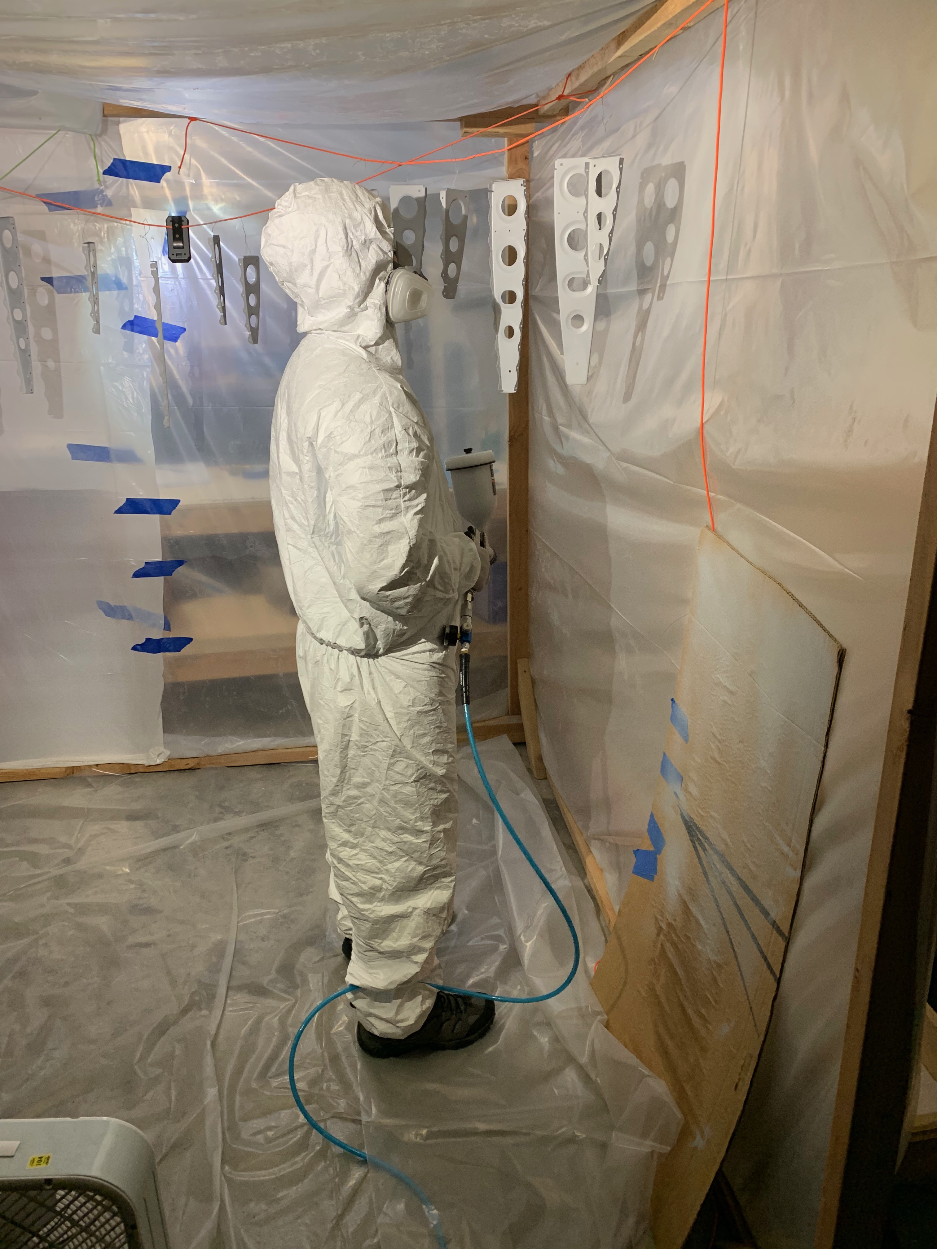
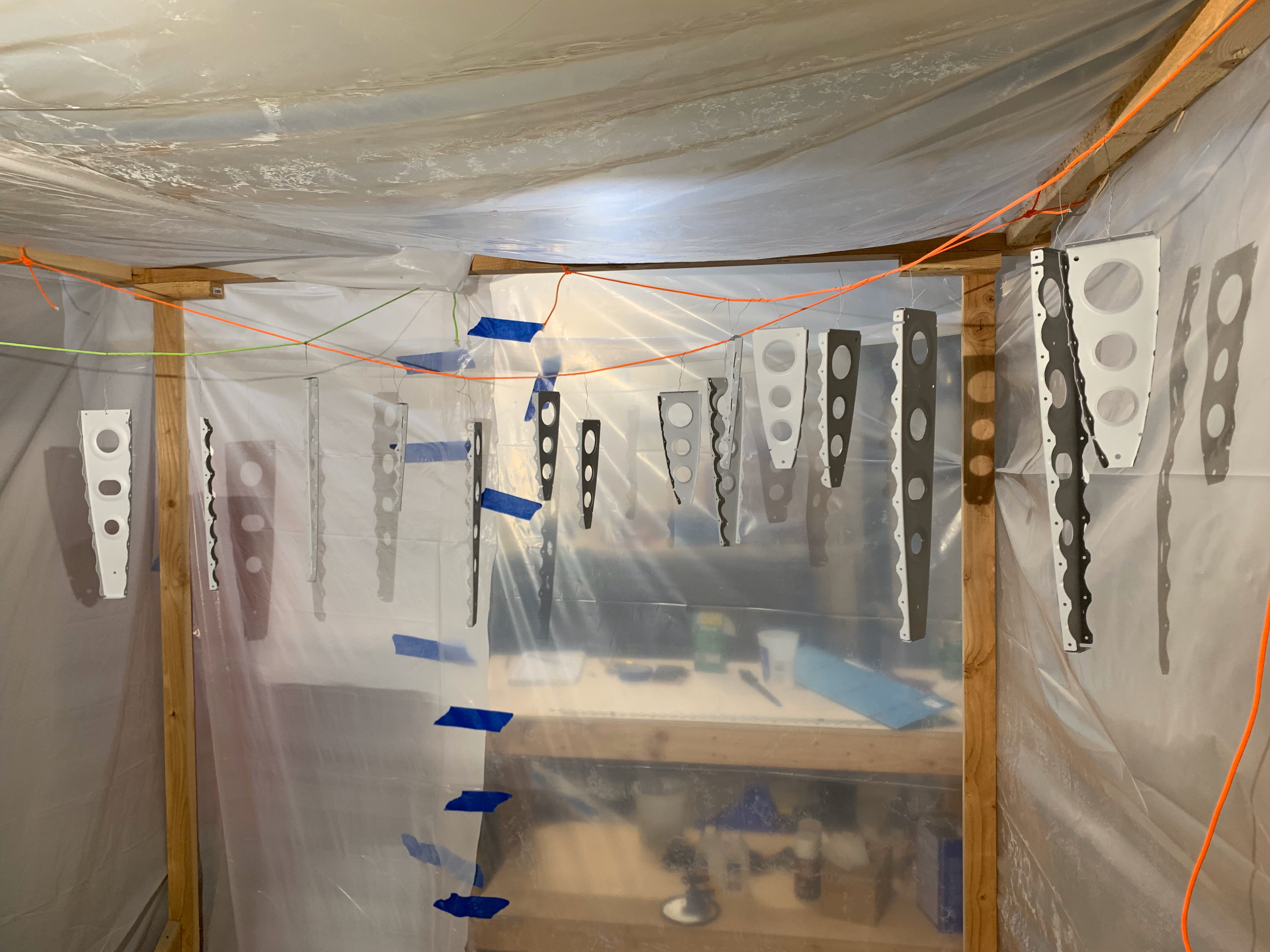
The parts actually turned out really nice – it took about three really thin coats to make all the shiny metal disappear.

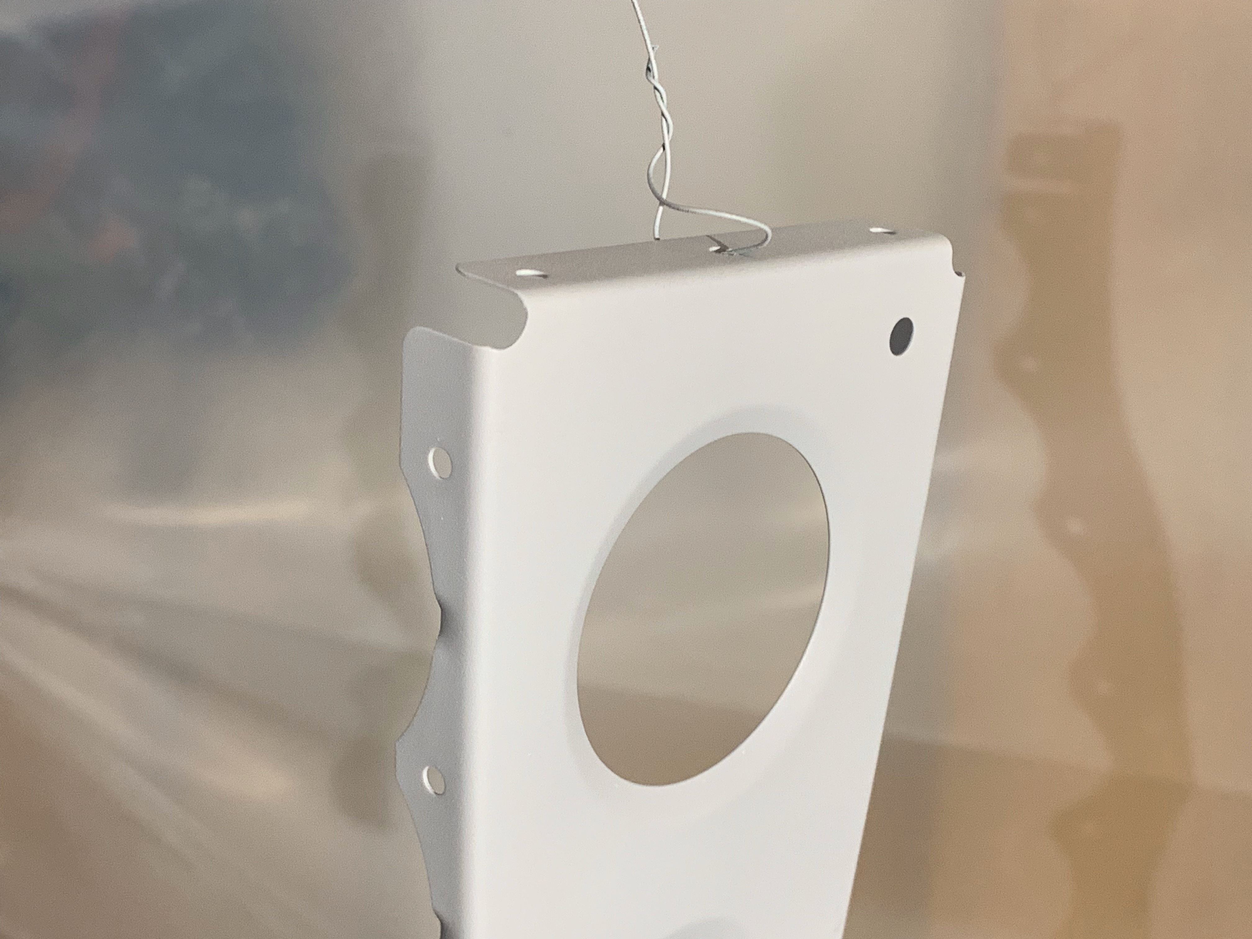
Honestly, other than the additional prep work this primer requires, I didn’t find the application process much more difficult. It was a little easier to generate “runs” with this stuff if sprayed on too thick – but I’m still new to spray applications in general.


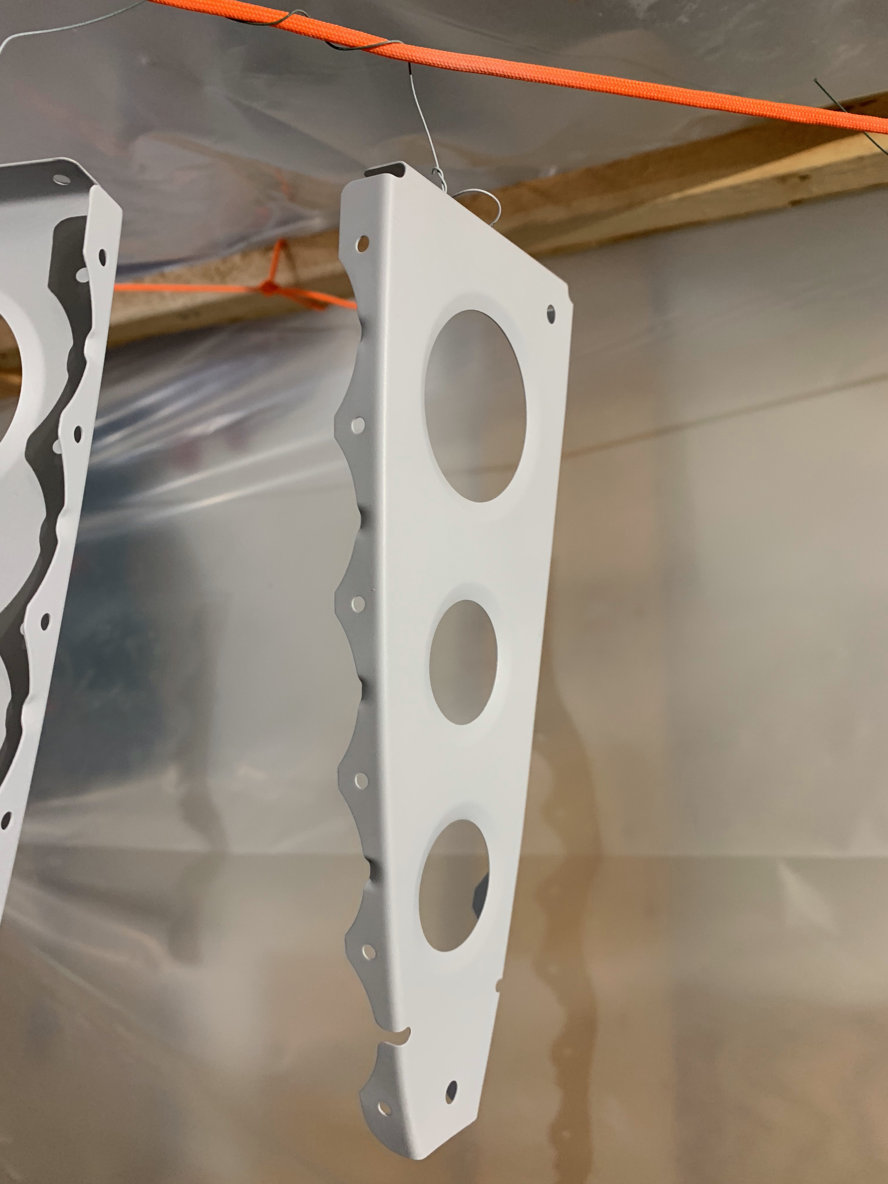
Priming the ribs was a big step forward! A few weeks later I moved on to deburring the large horizontal stabilator skins.

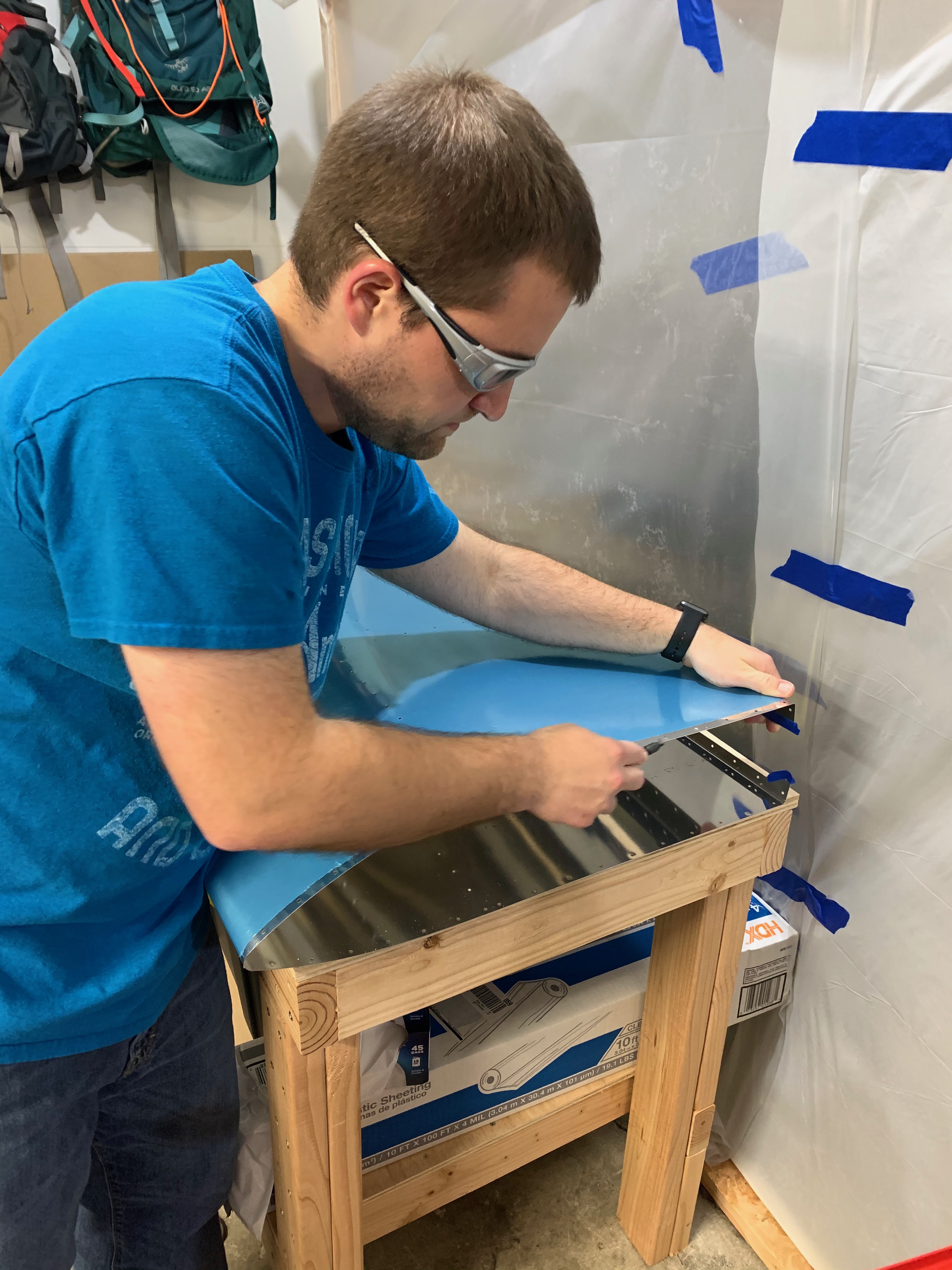
And really – that was it for 2019.

Now, here’s to building momentum in 2020! As I write this, it’s mid-April and I just cleaned out the garage. Had to catch up on the blog, re-read some plans, and refresh myself on some building material before I felt comfortable working on the parts again. Now the weather is shaping up, work has slowed down (partially due to the pandemic), and it is time to get building! Let’s go!

Rudder Final Assembly

Much like the anti-servo tab – rudder assembly is straightforward. A few larger solid rivets make life a little more difficult – unless you have a friend with a pneumatic squeezer.

No pictures of the skeleton, but here we are fastening the skin to the internal structure:

IMG_1157.jpeg

IMG_1161.jpeg

IMG_1178.jpeg

Ta-Da! Rudder done.

One thing I initially overlooked was the state of the powder-coated WD-1205 control horn. It’s a powder-coated part that Van’s says is ready to install, but there is a bit of it inside that isn’t really covered with much of anything. Other powder-coated parts have similar sections that end up not being covered. Advice for what to do is scattered in forums, but a quick consult with Axsys Air (thanks, Glenn!) convinced me to give priming the inside a shot since we’re already priming other things. I gave the inside a wipe-down with acetone and shot it with NAPA 7220 self-etching primer (spray can). Better than nothing, and adds just a little peace of mind for the steel part since we’re already doing the work of priming everything else.

IMG_1115.jpeg

Turns out that Glenn also said to be careful with the acetone. Of course, this important fact somehow slipped my mind when I noticed I got too much NAPA 7220 on the control horn in places I didn’t mask off very well. So what would one do? Wipe it down with acetone? NO! You shouldn’t. That will happily remove the finish and discolor the top of the nice white powder coat. You can actually see the yellow discoloration in the photo above. Of course, you may not see this until the next day when you’re ready to assemble everything…!

We double-checked that the powder coat still seemed intact and secure and searched for solutions. I decided to sand, clean with alcohol, let dry, and then use Dupli-Color multipurpose white and Dupli-Color clear coat. I practiced on some scrap – came out just fine. Not as hard as the original powder coat finish – but it will suffice for this fix.

Anti-Servo Tab Final Assembly

We did Section 8 (Anti-Servo tab) a bit out of order (most would do the Rudder first) – mostly because of an “oops” I describe in the final assembly of the rudder.

The “difficult” parts of putting the anti-servo tab together are discussed in a previous post – final assembly is relatively easy! The final assembly of the anti-servo tab was completed on March 24, 2019 with Lauren (a friend), Kelsey, and Steven.

In what feels like a strange move, the first step in riveting is to fasten the ribs to the top portion of the anti-servo tab skin. Immediately following (picture below), is the riveting the control horn to the inboard rib. This requires bending the bottom skin downward to insert a rivet squeezer. It’s a little awkward at best – and makes me wonder if the skin interferes with riveting to the rib. The only concern here was the aft most rivet seemed to pull the control horns a bit away from the rib – and we ended up with a .010-inch gap at the aft edge of the control horn. The forward portion is flush. One of the control horns ended up with a gap more severe during riveting – so we drilled it out and replaced the rivet. Still ended up with the .010-inch gap at the aft edge. I
tried to get pictures, but they just don’t do the situation justice. Build it and fly, as they say…

For the non-builder: the control horn is the piece sticking upward in the photo below – it’s what attaches to other pieces to move this anti-servo tab.

IMG_1117.jpeg

The rest of the anti-servo tab is super easy. Pop rivets all the way. Not even worth describing to you, so here are some action photos:

IMG_1123.jpeg

IMG_1127.jpeg

IMG_1132.jpegAnd that’s it, really! You end up with two anti-servo tabs. Each built as a mirror of the other.

IMG_1137.jpeg


Rudder and Anti-Servo Tab Parts Prep

Where have we been?

Took a bit of a break over Nov-Feb mostly due to my work (the garage temperature wasn’t particularly inviting either). We got back to “thinking about building” in late February and built momentum in March. We made (slow) progress on the Rudder, Anti-Servo Tab, and even the Horizontal Stabilator in that time. Progress was so slow that I often forgot to take a picture during a half hour worth of work.

Wing kit has been ordered with an estimated ship date of late May, so we need to get moving on the rest of this empennage kit!

Rudder

Using a bit of what was learned from the previous section, I employed the drill press for match-drilling the “spar caps” (structural reinforcements).

IMG_0386.jpeg

Using the drill press on the spar flanges is a bit more challenging, so we went with the pneumatic hand drill instead.

IMG_0395.jpeg

I’ll spare you pictures of deburring the part edges (boring enough that that we forgot to take them), but I’ll assure you plenty of time was spent cleaning things up with various deburring tools. It’s about this point in the build where I have realized that a smaller (than I expected) percentage of actual time is spent doing final assemblies, especially if you do a decent job deburring and priming. For some reason, friends appear most interested in doing the “fun” assembly stuff…!

Last step before assembly was priming all of those internal parts. The weather finally got warm enough in March that I was comfortable getting out the primer again. We were able to get most of the Rudder and Anti-Servo Tab parts done in this round, but lost out to the sunset.

IMG_1095.jpeg
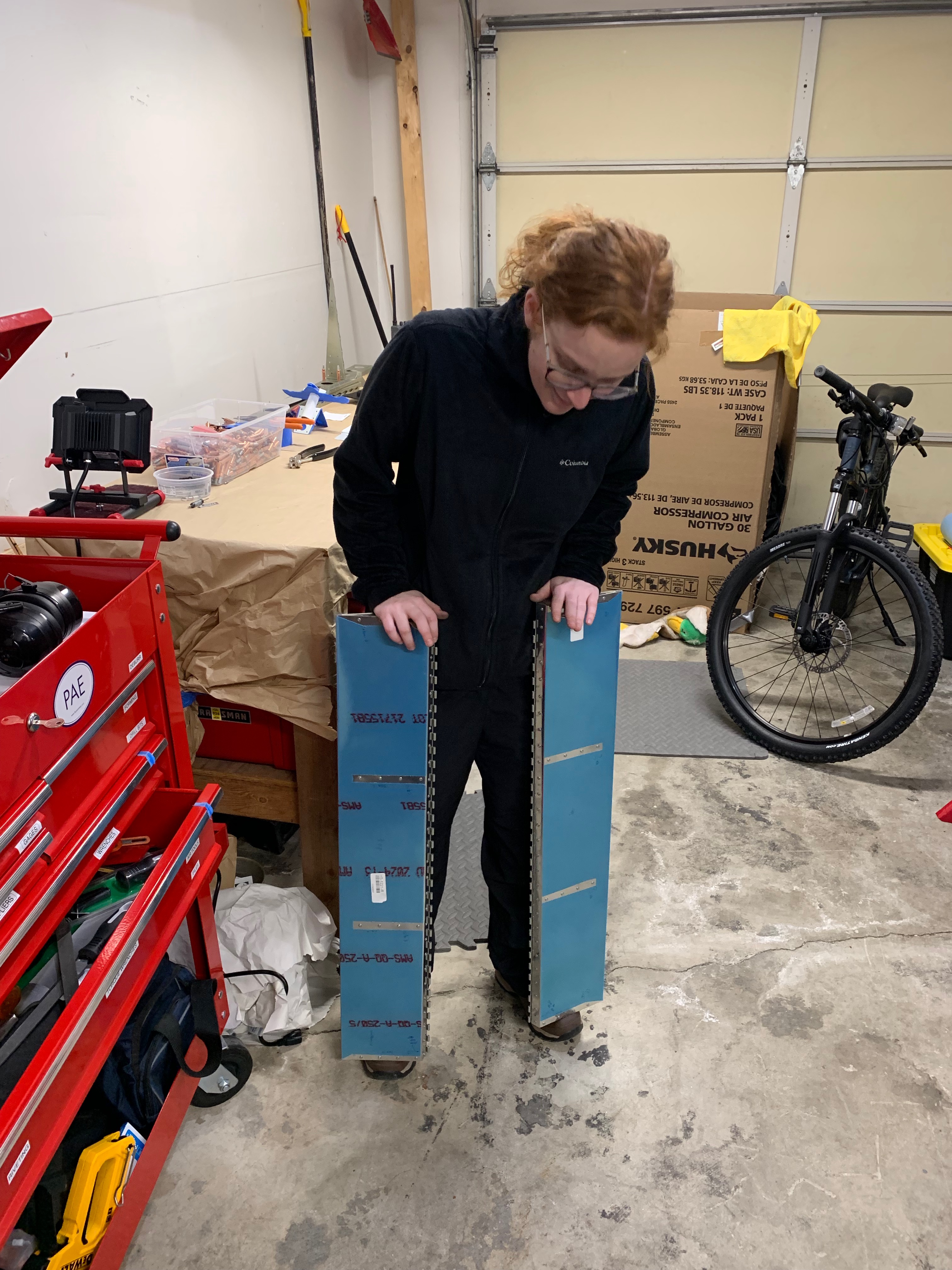
The rudder skin and a few other lagging parts were finished a few days after with a friend who was priming the final bits of his RV-14 vertical stabilizer. No pictures, as we were all too preoccupied with finding a local beer afterward (oops!)

Anti-Servo Tab (AST)

In parallel to the Rudder parts, we began prepping the Anti-Servo tab since it wasn’t quite warm enough to make priming easy.

For the uninitiated: The RV-12 has a full flying “stabilator” instead of a fixed horizontal stabilizer and elevator with trim tab that you would see on a Cessna 172. The entire pitch control surface moves when the pilot deflects the control stick. The Anti-Servo tab deflects in the same direction as the trailing edge of the stabilator to increase column force so that the aircraft isn’t too pitch-sensitive. A servo or “balance” tab would deflect in the opposite direction, working to decrease control forces (useful for higher-speed aircraft with higher aerodynamic loads). I’m too lazy to draw a cartoon for you, but Wikipedia is your friend.

You survived the jargon, have a picture!

IMG_0872.jpeg

The countersinking above was again a learning process. I screwed up the vertical spar’s original countersinking, and Kelsey took her shot at these control horns. These pieces connect to the anti-servo tab to move it in flight. We weren’t totally satisfied with our first round of countersinking, so we ordered new pieces from Van’s and did it better the second time. I’ve read that many builders feel like they built their airplane twice. Now I get it.

IMG_0871.jpeg

The anti-servo tabs are attached with and pivot around an aluminum piano hinge (shown above). The hinge is match-drilled with a metal guide that slides in between hinge spaces, shown above. The same is eventually done on the stabilator, and then the hinge halves are joined with a thick wire.

Kelsey did the bulk of the anti-servo tab skeleton work while I was busy in November (2018). I don’t have any fancy pictures of that work, but you can see some of the resulting parts that we were priming.

IMG_1108.jpg

We chose to prime as much of the anti-servo tab skin that we were able to shoot with the spray gun, as well as the edge that the piano hinge rests on. Same for the hinges – they were primed on the mating surface. The rest of the external surface will be painted professionally, so we left it as-is.

Vertical Stabilizer Final Assembly

This post encompasses the last 10-15 hours of final assembly in the vertical stabilizer. Minus the rudder hinge assemblies, we’ve fully completed “Section 6 – Vertical Stabilizer” in the plans.

We began final assembly of the vertical stabilizer the day after priming. As you’ll see throughout this post, the internal structure parts are covered in a thin green/gray layer of primer. Before priming, the parts were a shiny, almost mirror-like aluminum alloy covered with a layer of pure aluminum (“Alclad”). With priming complete, we actually have to step back in the assembly plans a bit and start fastening things together. Finally, we get to squeeze some rivets! First up: rudder hinge assemblies. The picture of me holding the completed bracket belies the frustration of actually squeezing those rivets by hand. The standard ATS squeezer could use a bit longer arms to increase the mechanical advantage.

Next, we fastened the parts that caused us so much trouble before: the Vertical Stabilizer Rear Spar, which has reinforcing “spar caps” and nutplates that are riveted on to accept the bolts for the rudder hinge assemblies. Below is the nutplate installation, which is slightly “floating” off the vertical spar surface (you can see the minor gaps). The gaps truly are small – and even though they aren’t fully flush with the surface, Van’s has said that <1/32” gap should be acceptable. I think all four were under .020”.

There are four ribs inside the vertical stabilizer. The lower two are attached to the forward and rear spars. You can see them attached in the photo below, where Kelsey is working to rivet the doublers onto the rear spar. A few more rivets, and we have the Vertical Stabilizer Skeleton fully assembled!

RV12iS_Log003 - 008

Sometimes you learn that you can screw up not just airplane parts, but the tools you’re working with too. Got some junk stuck inside of the rivet squeezer (don’t ask…), so this is me disassembling it. Having a set of various pin punches is pretty handy.

With a fully operational squeezer, it’s time to start riveting nutplates to the Main Skin. These nutplates will accept the screws that fasten the Forward Skin section to the main skin.

With the 18 nutplates installed, we can now begin preparations to rivet the main skin to the skeleton. In theory, you don’t have to cleco every hole – but I found that if there was a minor misalignment, it would probably make the final riveting a little easier.

With everything cleco’d together and the holes aligning, we can begin riveting! More than 250 rivets attach the main skin of the vertical stabilizer to the internal structure. Fortunately, they are all pull or pop-type rivets – and the Stanley ProSet XT1 rivet gun makes quick work of them. I can’t imagine doing these all by hand – and if you’re building an RV-12, I kindly would recommend you check yourself into the crazy clinic if you try save the money that you should be spending on a pneumatic rivet gun. I’m not convinced you have to buy the pricier Stanley one, but it sure is light, ergonomic, and easy to work with.

There’s nothing in the plans that technically requires you to assemble this vertically, but I would highly recommend it. Just make sure it’s not going to topple over.

Do not brandish your airplane parts about the garage to take strange pictures. Just because we did it doesn’t mean it’s a good idea. 🙂

Vertical Stabilizer Progress

Wow, we’ve been busy! Had some visitors and vacation time in the past couple of weeks, but we got back to building shortly after. This post encompasses ~30 hours of build work, up through priming the vertical stabilizer parts.

First up in the empennage plans is the Vertical Stabilizer. A large portion of the work involves the rear spar, to which most of the inner skeleton attaches. The spar is fairly thin, but is reinforced by “spar caps,” which are essentially doublers. The spar is pre-punched, but the spar caps require match drilling.

RV12iS_Log002 - 1

After match drilling, the plans call for countersinking a few holes on the front and rear spars to accept flush rivets. This is where our first trouble started. I took a shot at countersinking the rear spar’s six holes that are for flush rivets to the spar caps and ended up with terrible results. We didn’t have scrap to practice on, but we do now! New VS-1203 rear spar was ordered on a Sunday and arrived by Friday.

RV12iS_Log002 - 2.jpg

The countersunk holes chattered on me quite a bit (you can see the rough edges above). Turns out that it is difficult to get a nice countersink for the AN3 rivets when the sheet metal is at or near minimum the required thickness. Van’s recommends putting a piece of scrap behind the target hole and match-drilling then cleco-ing. The is allows scrap aluminum (or wood at the very least) behind the targeted piece to guide the pilot cutter and keep it centered. The scrap sheet should help prevent chattering and enlargement of the countersunk hole.

After practicing for awhile on the scrap spar (and not yet trying the above preferred methods) I still wasn’t satisfied with the success rate and asked Van’s if we could dimple the holes instead. Van’s approved, so the nutplate rivet holes on our new vertical stabilizer spar are dimpled instead of countersunk. This will require substitution of a slightly longer rivet than the plans call for since no metal was removed from the parts being fastened. Check your rivets for appropriate length before squeezing!

The ribs that attach to the spar and form the shape of the airfoil’s main skin require deburring and fluting (to straighten hole alignment) . Kelsey spent hours deburring the rib flanges and lightening holes – quite a monotonous job.

RV12iS_Log002 - 3

The vertical stabilizer skin consists of a main skin and a much smaller forward skin that is fastened with screws. To make the attachments flush, the skins are dimpled for the screws.

At this point, the major steps to complete the vertical stabilizer have been completed, and a test fit is in order. To do a test fit, everything is cleco’d together. If rib holes don’t align, they are fluted (or un-fluted) to line up the holes with the main skin. I’m not convinced that this ever comes out perfectly, so a tiny bit of mismatch is probably okay. Toward the leading edge, the ribs required some additional removal of material to fit inside the main skin’s pre-shaped curve. Overall, not too bad! But it takes awhile to insert and remove so many clecos!

RV12iS_Log002 - 6

Nothing has been permanently fastened together yet because we have chosen to prime the internal structure in an attempt to prevent corrosion in the airplane’s lifetime. Priming most of the aircraft structure is not required per plans, but it can and should add additional corrosion protection. This topic is hotly debated in the experimental aircraft community, so I’ll plan to write a longer explanation about what we chose to use and how we’re doing it. For those who can’t wait: We’re using Van’s-Recommended P60G2 Sherwin Williams industrial wash primer. It does require personal protective equipment, but it dries very quickly and forms a thin protective layer.

RV12iS_Log002 - 7.jpg

Above are the parts after priming, with gratuitous practice paper for adjusting the spray gun.

Next up: final assembly of the Vertical Stabilizer!

Empennage Kit Arrives

Our Empennage/Tailcone kit order was originally submitted on August 14th and processed the next day by Van’s Aircraft. We were told to expect a mid-September shipping date. Lead times were a little longer than normal for the kit because the RV-12iS was such a popular hit at Oshkosh this year (it was the “One Week Wonder, built in seven days at the event).

The kit was crated and shipped the week of August 27, a few weeks earlier than expected. For those who aren’t familiar with how this works: Van’s Aircraft fabricates and/or stocks the kit components at their factory. When someone orders a kit, they make sure they have all (or at least most) of the kit parts, then they package it up into a wooden crate that’s shipped via freight. A few parts were backordered, so they will ship separately later to complete the kit. In the meantime, we would be able to get started on the pieces we received in the first shipment.

With Labor Day causing some expected shipping delays, we received our RV-12 empennage kit crate on September 5, 2018. FedEx Freight did a great job at getting the crate into the garage. Some minor (forklift?) damage on the outside of the box turned out to be a non-issue, as huge boxes of rivets (12,500!) were on the other side.

Not the best of pictures, but I had to get back to work after accepting the delivery. The box was about 220 lbs, so kudos to a coworker who’s also building a Van’s RV-14 for helping me out.

We got straight to inventorying the parts that night – probably about 80% of them!

Finished the inventory and part shelving two days later. Here’s some of them, complete with a bit of garage clutter!

We have a bit of reading to do before starting the build process, but we’re off to a decent start!