Vertical Stabilizer Final Assembly

This post encompasses the last 10-15 hours of final assembly in the vertical stabilizer. Minus the rudder hinge assemblies, we’ve fully completed “Section 6 – Vertical Stabilizer” in the plans.

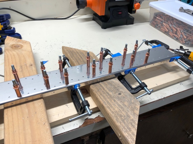
We began final assembly of the vertical stabilizer the day after priming. As you’ll see throughout this post, the internal structure parts are covered in a thin green/gray layer of primer. Before priming, the parts were a shiny, almost mirror-like aluminum alloy covered with a layer of pure aluminum (“Alclad”). With priming complete, we actually have to step back in the assembly plans a bit and start fastening things together. Finally, we get to squeeze some rivets! First up: rudder hinge assemblies. The picture of me holding the completed bracket belies the frustration of actually squeezing those rivets by hand. The standard ATS squeezer could use a bit longer arms to increase the mechanical advantage.

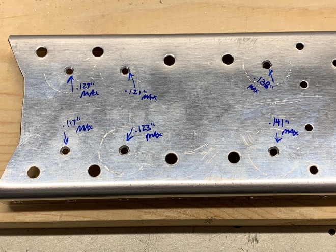
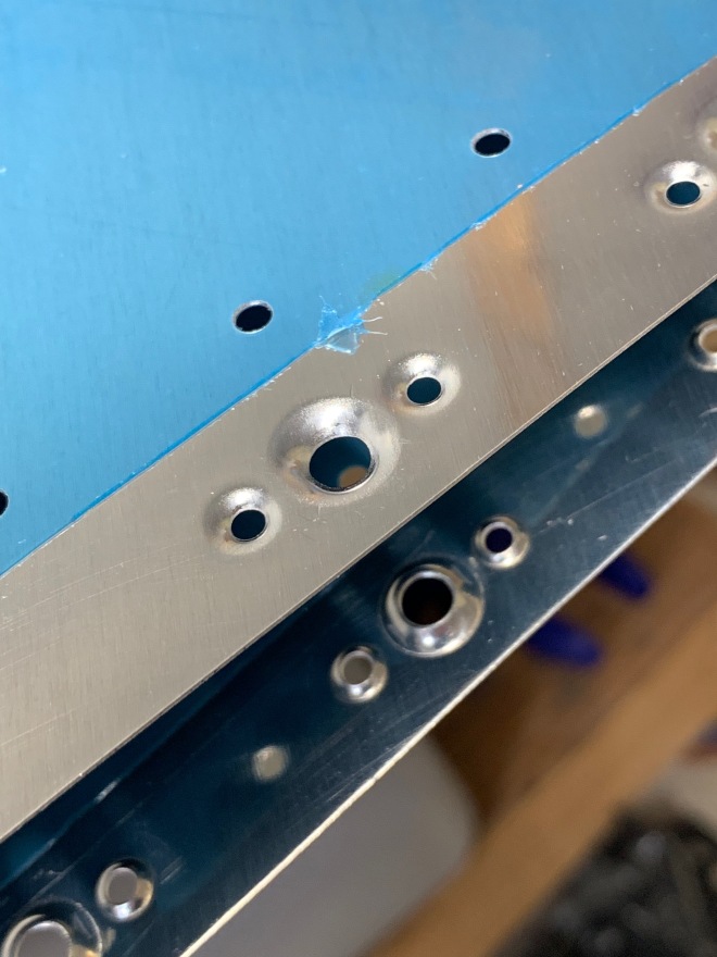
Next, we fastened the parts that caused us so much trouble before: the Vertical Stabilizer Rear Spar, which has reinforcing “spar caps” and nutplates that are riveted on to accept the bolts for the rudder hinge assemblies. Below is the nutplate installation, which is slightly “floating” off the vertical spar surface (you can see the minor gaps). The gaps truly are small – and even though they aren’t fully flush with the surface, Van’s has said that <1/32” gap should be acceptable. I think all four were under .020”.

There are four ribs inside the vertical stabilizer. The lower two are attached to the forward and rear spars. You can see them attached in the photo below, where Kelsey is working to rivet the doublers onto the rear spar. A few more rivets, and we have the Vertical Stabilizer Skeleton fully assembled!

RV12iS_Log003 - 008

Sometimes you learn that you can screw up not just airplane parts, but the tools you’re working with too. Got some junk stuck inside of the rivet squeezer (don’t ask…), so this is me disassembling it. Having a set of various pin punches is pretty handy.

With a fully operational squeezer, it’s time to start riveting nutplates to the Main Skin. These nutplates will accept the screws that fasten the Forward Skin section to the main skin.

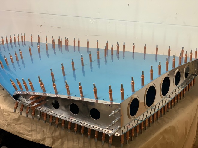
With the 18 nutplates installed, we can now begin preparations to rivet the main skin to the skeleton. In theory, you don’t have to cleco every hole – but I found that if there was a minor misalignment, it would probably make the final riveting a little easier.

With everything cleco’d together and the holes aligning, we can begin riveting! More than 250 rivets attach the main skin of the vertical stabilizer to the internal structure. Fortunately, they are all pull or pop-type rivets – and the Stanley ProSet XT1 rivet gun makes quick work of them. I can’t imagine doing these all by hand – and if you’re building an RV-12, I kindly would recommend you check yourself into the crazy clinic if you try save the money that you should be spending on a pneumatic rivet gun. I’m not convinced you have to buy the pricier Stanley one, but it sure is light, ergonomic, and easy to work with.

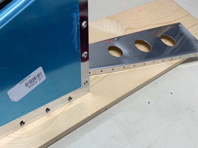
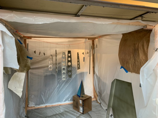
There’s nothing in the plans that technically requires you to assemble this vertically, but I would highly recommend it. Just make sure it’s not going to topple over.

Do not brandish your airplane parts about the garage to take strange pictures. Just because we did it doesn’t mean it’s a good idea. 🙂

Vertical Stabilizer Progress

Wow, we’ve been busy! Had some visitors and vacation time in the past couple of weeks, but we got back to building shortly after. This post encompasses ~30 hours of build work, up through priming the vertical stabilizer parts.

First up in the empennage plans is the Vertical Stabilizer. A large portion of the work involves the rear spar, to which most of the inner skeleton attaches. The spar is fairly thin, but is reinforced by “spar caps,” which are essentially doublers. The spar is pre-punched, but the spar caps require match drilling.

RV12iS_Log002 - 1

After match drilling, the plans call for countersinking a few holes on the front and rear spars to accept flush rivets. This is where our first trouble started. I took a shot at countersinking the rear spar’s six holes that are for flush rivets to the spar caps and ended up with terrible results. We didn’t have scrap to practice on, but we do now! New VS-1203 rear spar was ordered on a Sunday and arrived by Friday.

RV12iS_Log002 - 2.jpg

The countersunk holes chattered on me quite a bit (you can see the rough edges above). Turns out that it is difficult to get a nice countersink for the AN3 rivets when the sheet metal is at or near minimum the required thickness. Van’s recommends putting a piece of scrap behind the target hole and match-drilling then cleco-ing. The is allows scrap aluminum (or wood at the very least) behind the targeted piece to guide the pilot cutter and keep it centered. The scrap sheet should help prevent chattering and enlargement of the countersunk hole.

After practicing for awhile on the scrap spar (and not yet trying the above preferred methods) I still wasn’t satisfied with the success rate and asked Van’s if we could dimple the holes instead. Van’s approved, so the nutplate rivet holes on our new vertical stabilizer spar are dimpled instead of countersunk. This will require substitution of a slightly longer rivet than the plans call for since no metal was removed from the parts being fastened. Check your rivets for appropriate length before squeezing!

The ribs that attach to the spar and form the shape of the airfoil’s main skin require deburring and fluting (to straighten hole alignment) . Kelsey spent hours deburring the rib flanges and lightening holes – quite a monotonous job.

RV12iS_Log002 - 3

The vertical stabilizer skin consists of a main skin and a much smaller forward skin that is fastened with screws. To make the attachments flush, the skins are dimpled for the screws.

At this point, the major steps to complete the vertical stabilizer have been completed, and a test fit is in order. To do a test fit, everything is cleco’d together. If rib holes don’t align, they are fluted (or un-fluted) to line up the holes with the main skin. I’m not convinced that this ever comes out perfectly, so a tiny bit of mismatch is probably okay. Toward the leading edge, the ribs required some additional removal of material to fit inside the main skin’s pre-shaped curve. Overall, not too bad! But it takes awhile to insert and remove so many clecos!

RV12iS_Log002 - 6

Nothing has been permanently fastened together yet because we have chosen to prime the internal structure in an attempt to prevent corrosion in the airplane’s lifetime. Priming most of the aircraft structure is not required per plans, but it can and should add additional corrosion protection. This topic is hotly debated in the experimental aircraft community, so I’ll plan to write a longer explanation about what we chose to use and how we’re doing it. For those who can’t wait: We’re using Van’s-Recommended P60G2 Sherwin Williams industrial wash primer. It does require personal protective equipment, but it dries very quickly and forms a thin protective layer.

RV12iS_Log002 - 7.jpg

Above are the parts after priming, with gratuitous practice paper for adjusting the spray gun.

Next up: final assembly of the Vertical Stabilizer!