Where have we been?
Took a bit of a break over Nov-Feb mostly due to my work (the garage temperature wasn’t particularly inviting either). We got back to “thinking about building” in late February and built momentum in March. We made (slow) progress on the Rudder, Anti-Servo Tab, and even the Horizontal Stabilator in that time. Progress was so slow that I often forgot to take a picture during a half hour worth of work.
Wing kit has been ordered with an estimated ship date of late May, so we need to get moving on the rest of this empennage kit!
Rudder
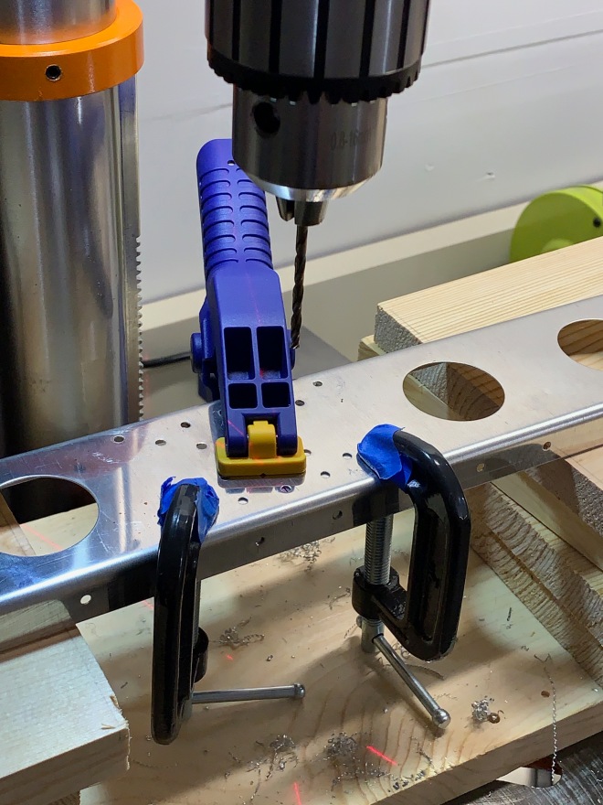
Using a bit of what was learned from the previous section, I employed the drill press for match-drilling the “spar caps” (structural reinforcements).
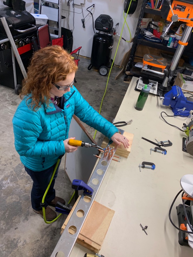
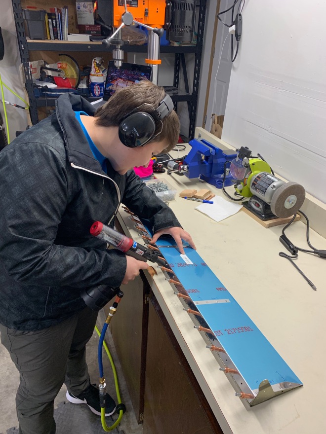
Using the drill press on the spar flanges is a bit more challenging, so we went with the pneumatic hand drill instead.
I’ll spare you pictures of deburring the part edges (boring enough that that we forgot to take them), but I’ll assure you plenty of time was spent cleaning things up with various deburring tools. It’s about this point in the build where I have realized that a smaller (than I expected) percentage of actual time is spent doing final assemblies, especially if you do a decent job deburring and priming. For some reason, friends appear most interested in doing the “fun” assembly stuff…!
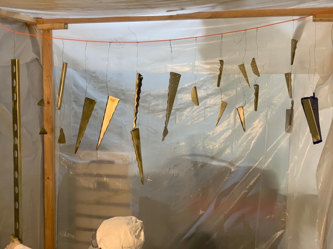
Last step before assembly was priming all of those internal parts. The weather finally got warm enough in March that I was comfortable getting out the primer again. We were able to get most of the Rudder and Anti-Servo Tab parts done in this round, but lost out to the sunset.
 The rudder skin and a few other lagging parts were finished a few days after with a friend who was priming the final bits of his RV-14 vertical stabilizer. No pictures, as we were all too preoccupied with finding a local beer afterward (oops!)
Anti-Servo Tab (AST)
In parallel to the Rudder parts, we began prepping the Anti-Servo tab since it wasn’t quite warm enough to make priming easy.
For the uninitiated: The RV-12 has a full flying “stabilator” instead of a fixed horizontal stabilizer and elevator with trim tab that you would see on a Cessna 172. The entire pitch control surface moves when the pilot deflects the control stick. The Anti-Servo tab deflects in the same direction as the trailing edge of the stabilator to increase column force so that the aircraft isn’t too pitch-sensitive. A servo or “balance” tab would deflect in the opposite direction, working to decrease control forces (useful for higher-speed aircraft with higher aerodynamic loads). I’m too lazy to draw a cartoon for you, but Wikipedia is your friend.
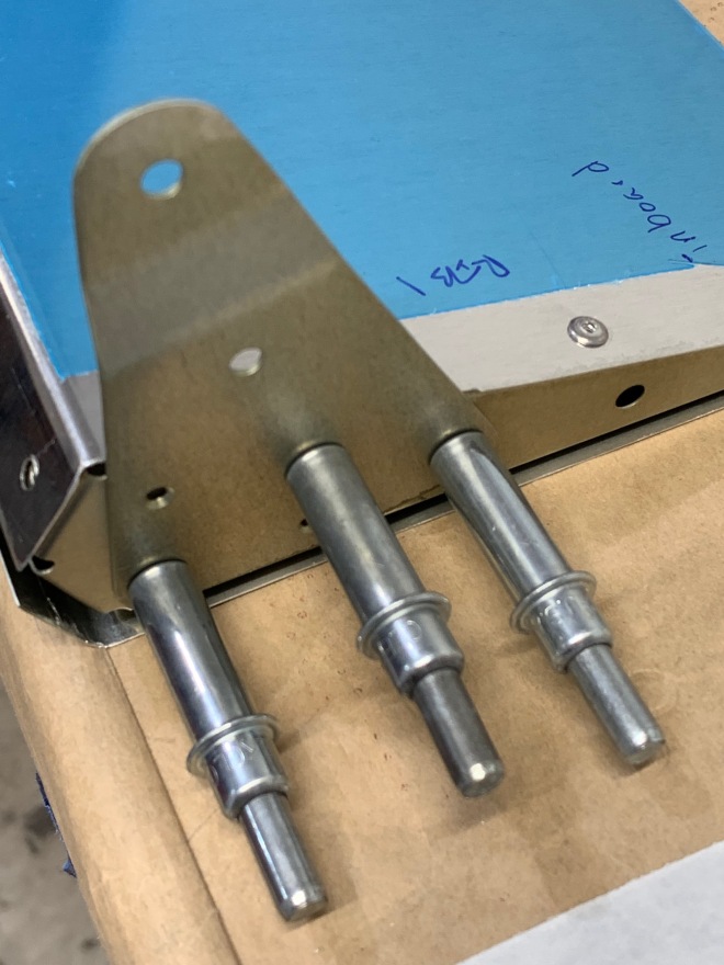
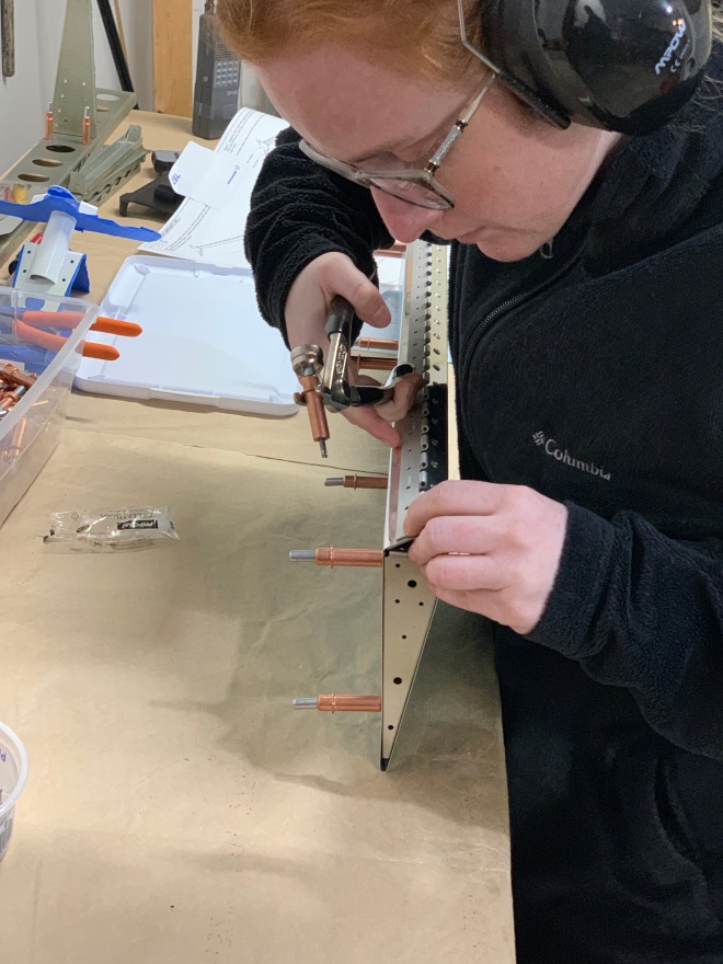
You survived the jargon, have a picture!
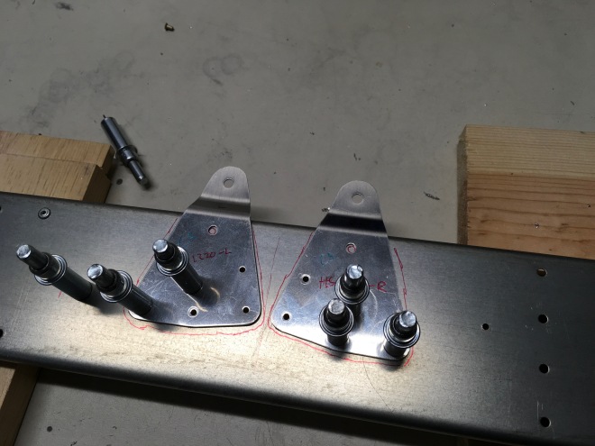
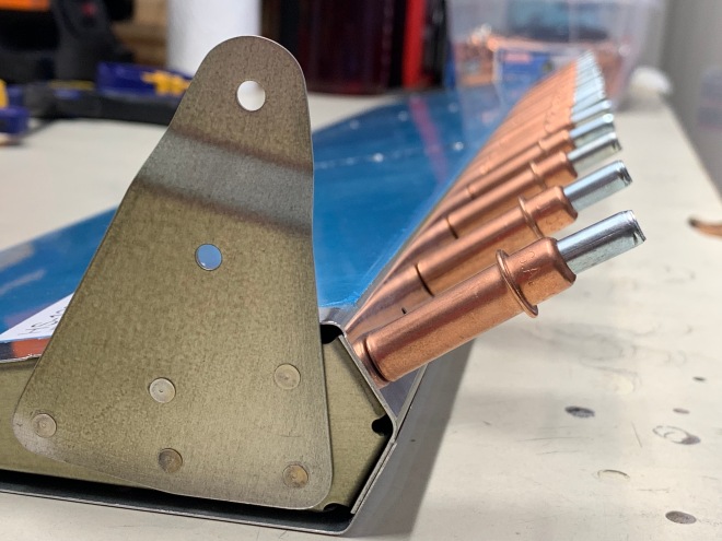
The countersinking above was again a learning process. I screwed up the vertical spar’s original countersinking, and Kelsey took her shot at these control horns. These pieces connect to the anti-servo tab to move it in flight. We weren’t totally satisfied with our first round of countersinking, so we ordered new pieces from Van’s and did it better the second time. I’ve read that many builders feel like they built their airplane twice. Now I get it.
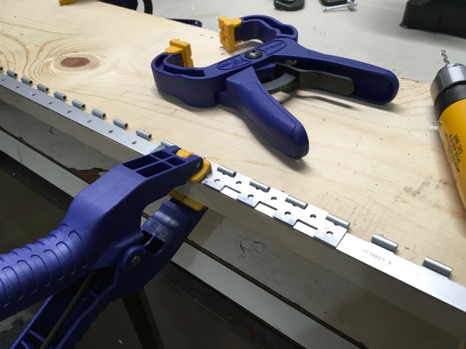
The anti-servo tabs are attached with and pivot around an aluminum piano hinge (shown above). The hinge is match-drilled with a metal guide that slides in between hinge spaces, shown above. The same is eventually done on the stabilator, and then the hinge halves are joined with a thick wire.
Kelsey did the bulk of the anti-servo tab skeleton work while I was busy in November (2018). I don’t have any fancy pictures of that work, but you can see some of the resulting parts that we were priming.
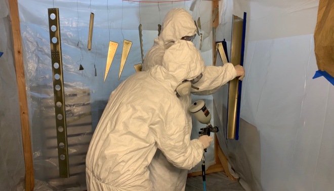
We chose to prime as much of the anti-servo tab skin that we were able to shoot with the spray gun, as well as the edge that the piano hinge rests on. Same for the hinges – they were primed on the mating surface. The rest of the external surface will be painted professionally, so we left it as-is.

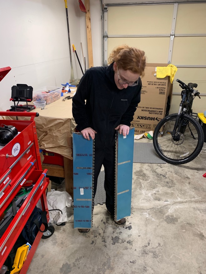
 And that’s it, really! You end up with two anti-servo tabs. Each built as a mirror of the other.